49
EN
TIG modes
Safety
WARNING!
Danger from incorrect operation.
Possible serious injury and damage to property.
► Do not use the functions described here until you have read and completely under-
stood these Operating Instructions.
► Do not use the functions described here until you have fully read and understood all of
the Operating Instructions for the system components, in particular the safety rules!
See the "The Setup menu" section for information on the settings, setting range and units
of measurement of the available welding parameters.
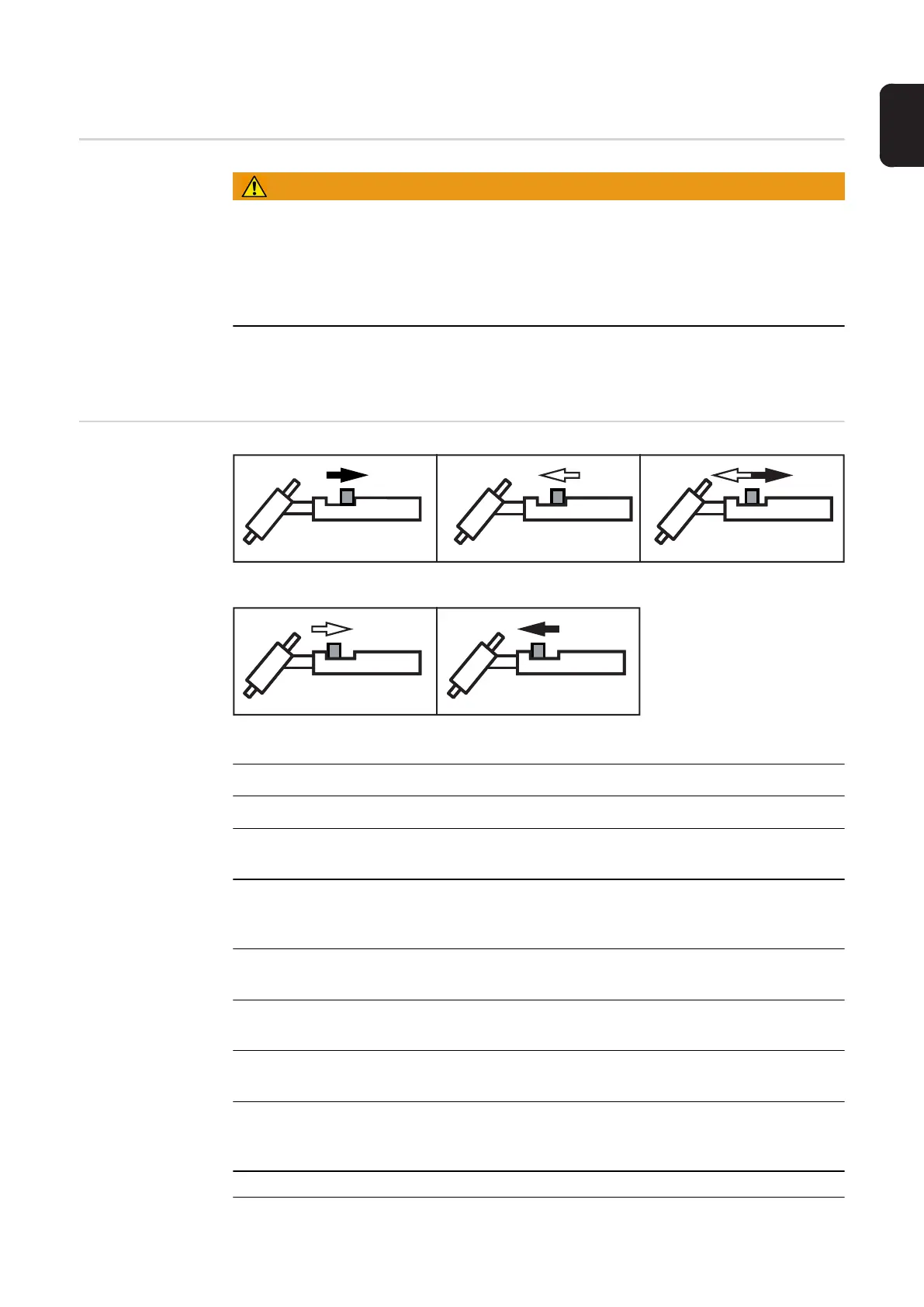
Symbols and
their explanations
Press and hold the torch trigger | Release the torch trigger | Press the torch trigger briefly (< 0.5 s)
Press and hold the torch trigger | Release the torch trigger
GPr Gas pre-flow time
SPt Spot welding time
I
S
Starting-current phase:
Carefully warm up with low welding current to position the filler metal correctly
I
E
Final current phase:
To avoid local overheating of the base material by heat accumulation at the end of
the welding. This eliminates any risk of weld seam drop-through.
UP UpSlope phase:
Continuous increase of the starting current to the main current (welding current) I1
DOWN DownSlope phase:
Continuous reduction of the welding current to the final current
I
1
Main current phase (welding current phase):
Uniform thermal input into the base material heated by advancing heat
I
2
Reduced current phase:
Intermediate lowering of the welding current in order to prevent any local overheat-
ing of the base material
GPO Gas post-flow time