MA-033 Rev. 14.0, 12-Nov-18
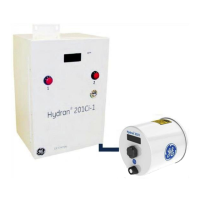
Hydran* 201i Instruction Manual
4–20 mA, 0–2000 ppm range
High and High-High alarms duplicate alarms in H201Ti: Gas
level, hourly and daily trends
Duplicates alarm in H201Ti: Power failure, loss of
communications, sensor and other system malfunctions; upon
system fault, analog outputs are set to zero and display is
blanked
Gas High, Gas High-High and System Fail
One NO and one NC contacts (type C) per alarm
Resistive load: 3A @ 250 VAC; 3A @ 30 VDC
Illuminated Push
Buttons (alarm
Indicators)
2 illuminated door-mounted push-buttons (gas High and High-
High alarms)
Latched on when corresponding alarm condition is detected
Turned off by pushing button when alarm condition is cleared
Connects with one H201Ti
2,000 Vac RMS isolated
3-twisted-pairs (16 or 18 AWG) cable with overall shield is
required
Maximal length (all cables added up): 1,200 m (4,000 ft)
Power supply: Separate, isolated, impedance-protected, +15 Vdc
RS-485 Local
Network Link
(Isolated)
Standard RS-485 communication port allows daisy-chaining of
up to 32 H201Ci Controllers (H201Ci-C’s and/or H201Ci-1’s) via
the Main Terminal Block
One twisted triad (16 or 18 AWG) with overall shield required
Maximal total daisy-chain length: 1,200 m (4,000 ft)
Standard RS-232 port (DB-9 connector), or standard USB link
(type-B connector)
Allows serial communications with a local host computer (or
remotely with optional modem)
Any H201Ti can be accessed through any H201Ci Controller in
the local network

 Loading...