Chapter 9 Page no. 1080
JC-TSG-A-020.fm
GE Healthcare Senographe DS
Revision 1 Service Information and Procedures Class A 2385072-16-8EN
Job Card TSG A020 - Generator Power-Up Sequence Flow Charts
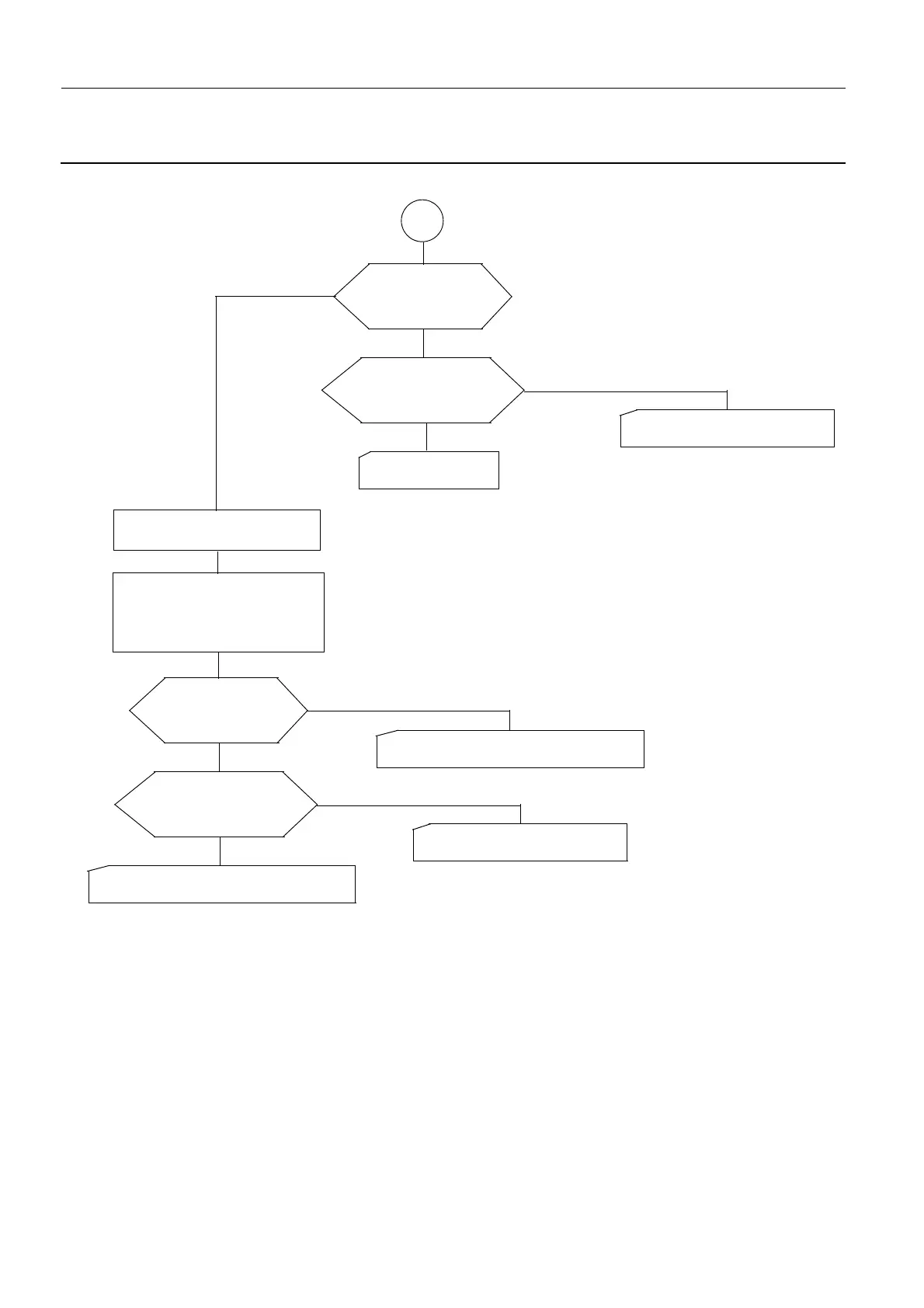
2-11 Main Power Contact K1 Engaged but Console Beeps at 1 s Intervals – E
E
200PL2: voltage
between TP4 and
0VV at 12 V?
Yes
No
Continuity between
200PL1 XJ1 pin 23 and
400PL1 XJ1 pin 23 OK?
Yes
Change 400PL1.
(DR406 - page 1569)
No
Change cable between 200PL1
XJ1 and 400PL1 XJ1.
Disconnect the cable from
200PL1 connector XJ11.
Connect voltmeter between
200PL1 XJ11 pin 12 and 0VV.
(
Note: pin 1 is marked and at
top left, pin 12 is bottom right).
Measured voltage
greater than 26 V?
Yes
No
Continuity OK in cable
between 200PL1 XJ11
and 200PL2 XJ2?
Yes
Change 200PL2 and reconnect cable
between 200PL1 XJ11 and 200PL2 XJ2.
No
Change cable between 200PL1
XJ11 and 200PL2 XJ2.
Change 200PL1 and reconnect cable
between 200PL1 XJ11 and 200PL2 XJ2.

 Loading...


