GE Healthcare Senographe DS
Revision 1 Service Information and Procedures Class A 2385072-16-8EN
Central Listing
Page no. 279 Chapter 3
Indicators and Switches.fm
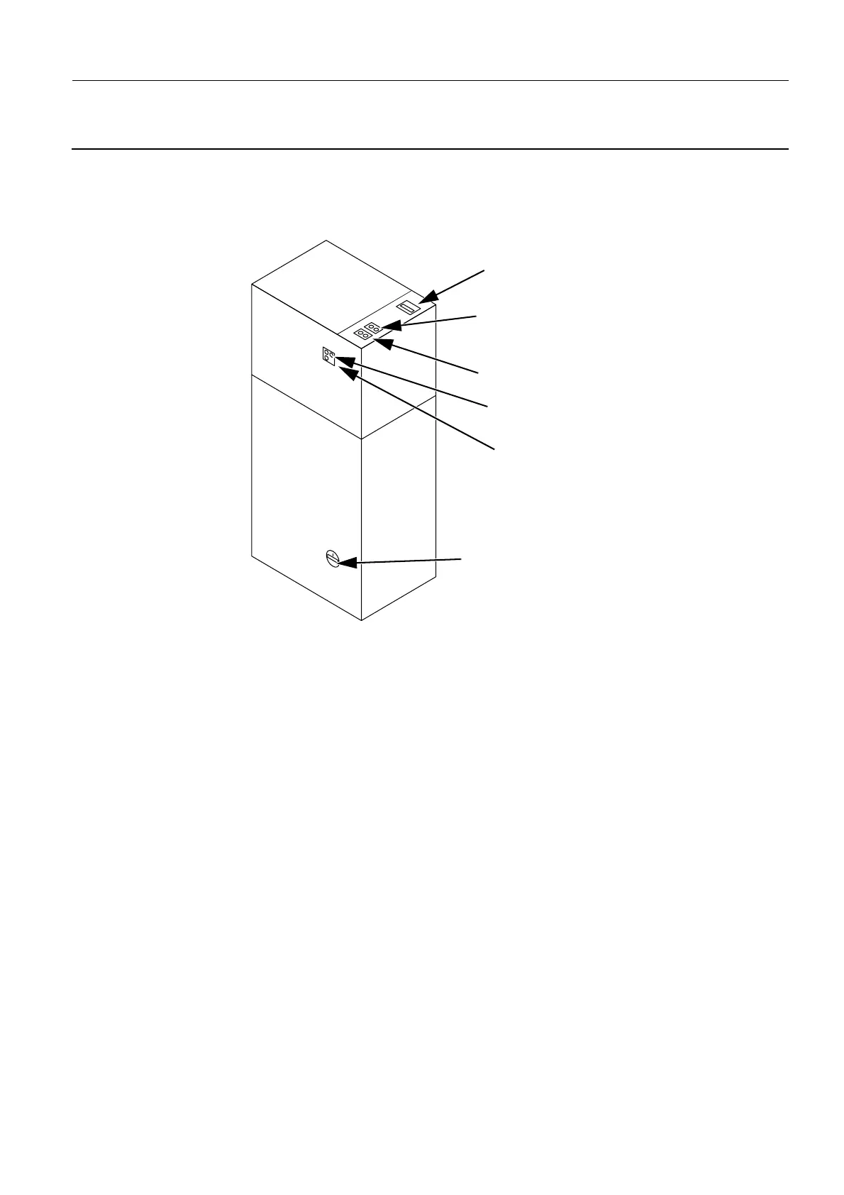
3. GENERATOR CABINET CIRCUIT BREAKERS
The power control buttons on the top of the Generator allow you to power on/off each of the labeled com-
ponents, so that you can isolate them as required. Except for the UPS push-button, the other push-but-
tons contain a second indicator light to the right-hand side of the push-button, and function as follows:
• the left-hand side push button toggles on/off the power to/from the component
• when power is applied to the component the left-hand side push-button is illuminated green and the
right-hand side light is not illuminated
• when power is not applied to the component the right-hand side light is illuminated yellow indicating
that the component is in standby, and the left-hand side push button is not illuminated
The UPS indicator light is off during normal operation when the system is powered up, during which time
it is charging. If the mains AC supply power to the Senographe system is suddenly cut, the UPS supplies
power to the Control Station components for a few minutes. During this time, the UPS indicator light is
illuminated.
MDR Breaker
Generator Breaker
Conditioner Button
Detector Supply Button
Control Station Button
UPS Button
Generator
Conditioner
and MDR

 Loading...


