GE Healthcare Senographe DS
Revision 1 Service Information and Procedures Class A 2385072-16-8EN
Job Card D/R A227 - Rotation Potentiometer
Page no. 1241 Chapter 9
JC-DR-A-227.fm
6-2 Reassembly of the Rotation Potentiometer
Reverse the disassembly procedure.
Add the following steps to the reassembly procedure:
• Turn the potentiometer axis to one of its travel limits, then make
five turns in the other way (approximately half way).
• Apply blue Loctite on the threads of both securing screws (2 and
3) before tightening them.
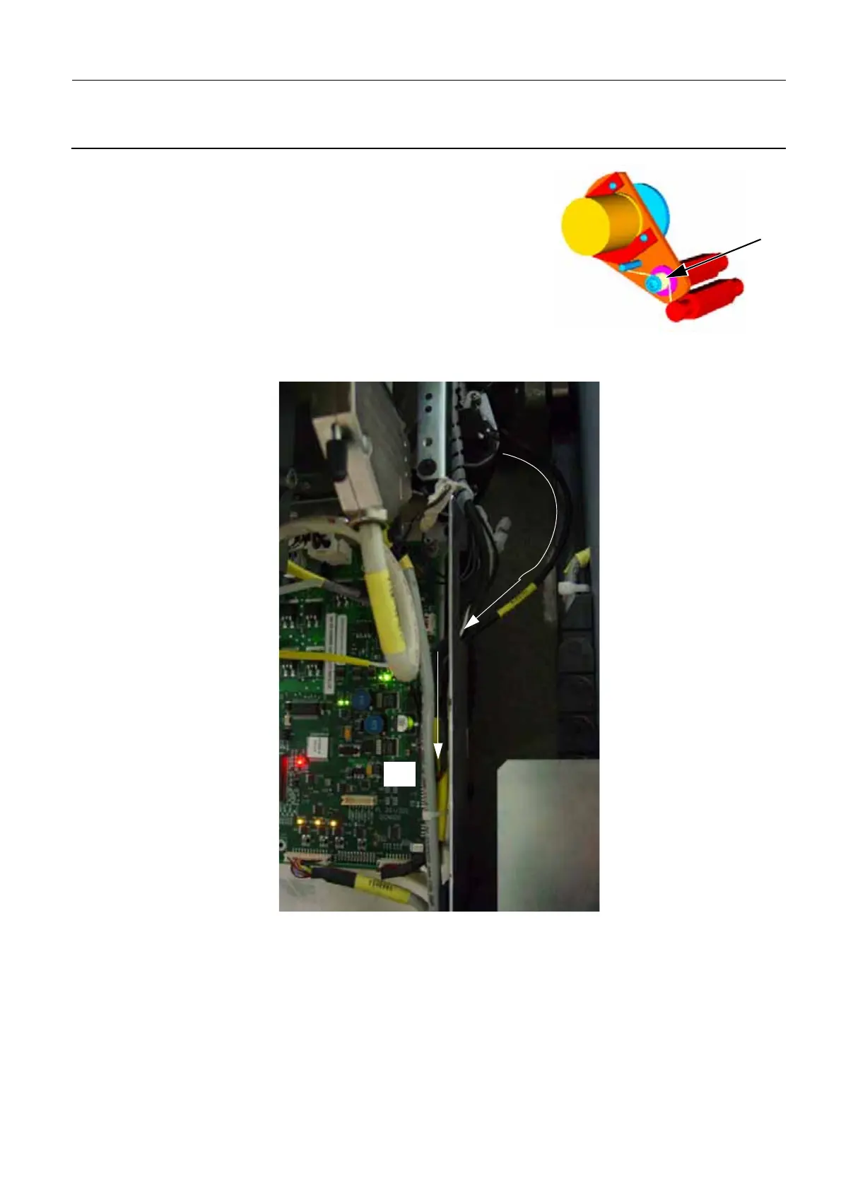
• When the Potentiometer and its support plate are reassembled
in the column, place the spring (4) as shown in the illustration.
• Route the Potentiometer cable (W220) as shown below, and plug it into the J11 connector on the
Rotation Board.
6-3 Check the Rotation Movement
1. Move the compression paddle out of compression. Then check that all four sets of arm left/right con-
trol buttons are operational (check each button for arm rotation movement).
2. Rotate the arm to its left and right limits. Software preset limits should stop movement (185° counter-
clockwise, 165° clockwise).
3. During arm movement, check for any noise that indicates excessive friction or binding.
4
J11

 Loading...


