Chapter 9 Page no. 1274
JC-DR-A-232.fm
GE Healthcare Senographe DS
Revision 1 Service Information and Procedures Class A 2385072-16-8EN
Job Card D/R A232 - Lift Screw Assembly
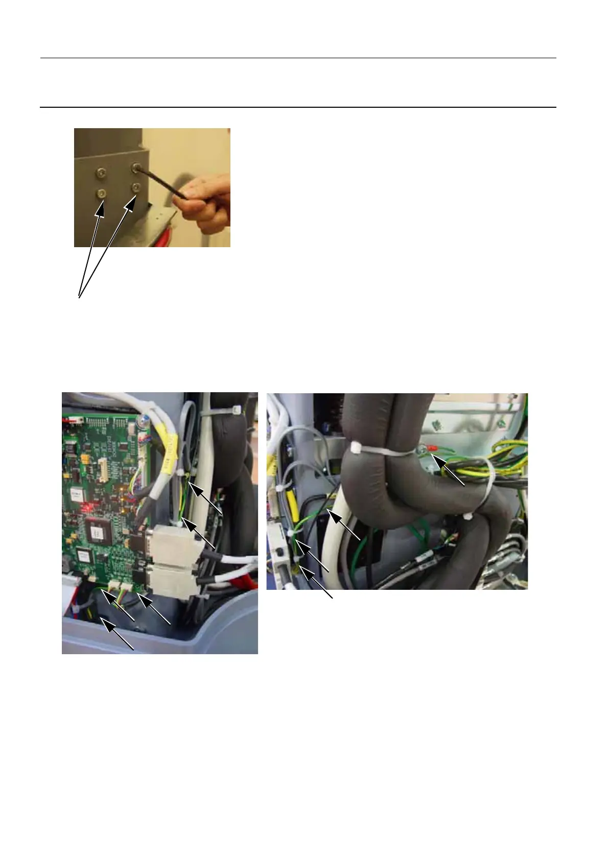
"cross" order top left, bottom right, bottom left, top right.
13. Replace the Lift Board that you originally had removed (refer to Job Card D/R A201 - Lift Board on
page 1161). The referenced Job Card instructs you how to connect all the cables back to the Lift
Board.
14. If you are changing a Type 2 Lift Screw Assembly, route and connect the Lift Motor earth cable to the
bottom left corner of the Detector Power Supply plate.
If you are changing a Type 3 Lift Screw Assembly, route and connect the Lift Motor earth cable to the
bottom left corner of the Detector Power Supply plate, and connect the brake cable to the J6 connec-
tor on the Lift Board.
15. Replace the curtains (refer to Job Card PHY A044 - Remove/Reinstall Gantry Covers on page 523).
16. If the Type 2 Lift Screw Assembly also had a Top Brake installed, re-intsall the Lift Screw Assembly
Brake (refer to Re-assembly of the new Gantry Lift Screw Brake on page 1283 in Job Card D/R A233
- Lift Screw Assembly Top Brake.
10

 Loading...


