Chapter 9 Page no. 1298
JC-DR-A-244.fm
GE Healthcare Senographe DS
Revision 1 Service Information and Procedures Class A 2385072-16-8EN
Job Card D/R A244 - Compression Motor with Encoder and Compression Belt
6 PROCEDURE
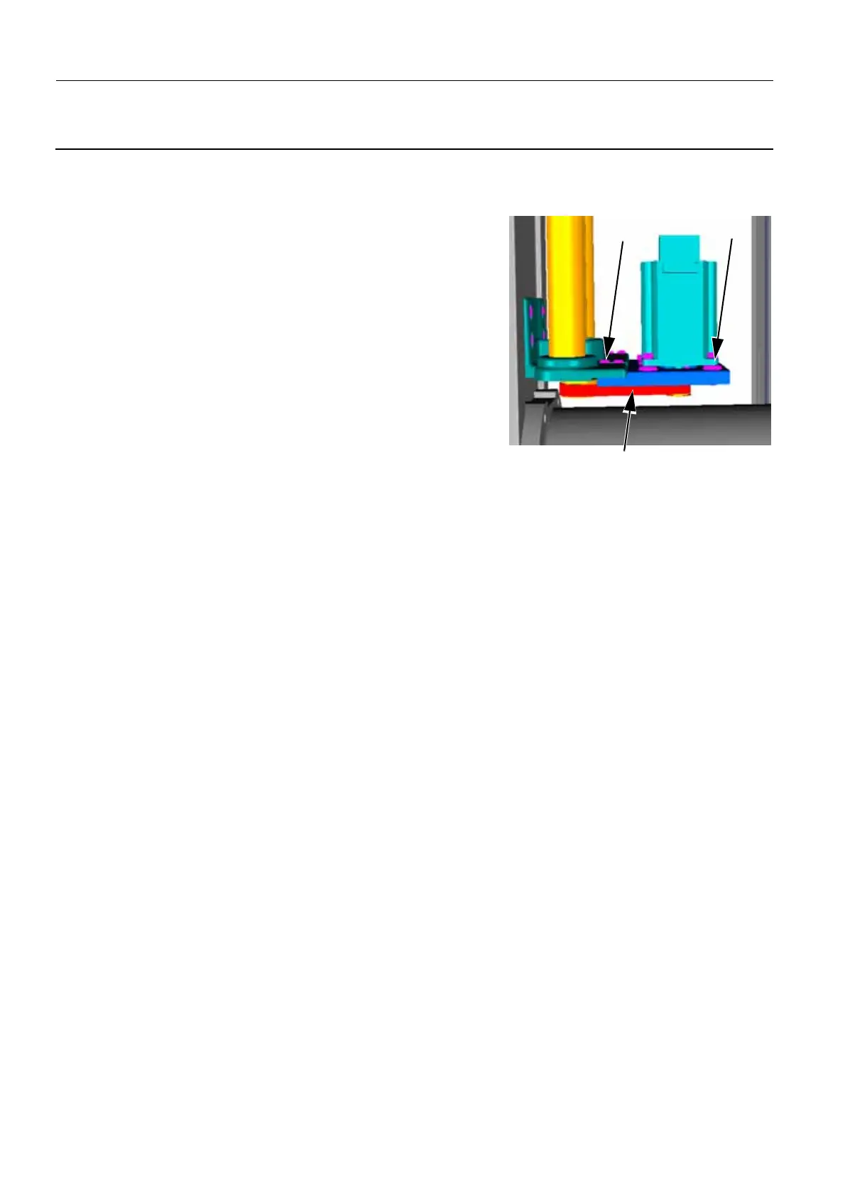
6-1 Disassembly of the Compression Belt
1. Remove the four screws (2) securing the Motor and its sup-
porting plate (3 mm allen wrench).
2. Disengage the Belt (4) from the gears.
3. Remove the Belt.
6-2 Disassembly of the Compression Motor
1. Unplug the Motor cable W301 from the Compression Board
(connector J3).
2. Remove the motor from its supporting plate, release the four
screws (3) (3 mm allen wrench and 7 mm open ended
wrench).
3. Unplug the encoder cable W302 from the Compression Board (Connector J4).
4. Release the screw securing the gear and the motor (2 mm allen wrench).
5. Extract the gear with a hub extractor (and a 17 mm open-ended wrench).
6-3 Reassembly of the Compression Motor and Belt
• Reverse the disassembly procedure and add the following step to the reassembly procedure:
• Apply blue Loctite on the threads of the four screws securing the supporting plate and on the
threads of the screw securing the motor and the gear before tightening them.
• Check manually that the Belt is tight enough.
6-4 Check the Compression Movement
1. Check that both sets of compression/decompression pedals and the manual compression knobs
located on the paddle holder all function correctly. That is, the paddle moves up or down in response
to each control.
2. Use the mammography compression scale placed between the Bucky and the compression paddle
to check calibration of the compression force display on the Gantry readout. Measure one point at
5 daN and one point at 15 daN. The value on the Gantry readout must agree within ±1 daN. If it does
not, perform Job Card CAL A048 - Calibration of Compression Force Sensor on page 1709.
Note:
If the recommended compression measurement tool is not available, this verification can be done
by lowering the paddle close to the top surface of the Bucky, installing the magnification device in
the upper pair of holes, and connecting a spring dynamometer (calibrated from 0 kg to 15 kg) be-
tween the compression paddle and the magnification device.
7 COMPLETION
None
2
3
4

 Loading...


