Chapter 9 Page no. 1362
JC-DR-A-265.fm
GE Healthcare Senographe DS
Revision 1 Service Information and Procedures Class A 2385072-16-8EN
Job Card D/R A265 - Tilt Motor and Drive Assembly
6 PROCEDURE
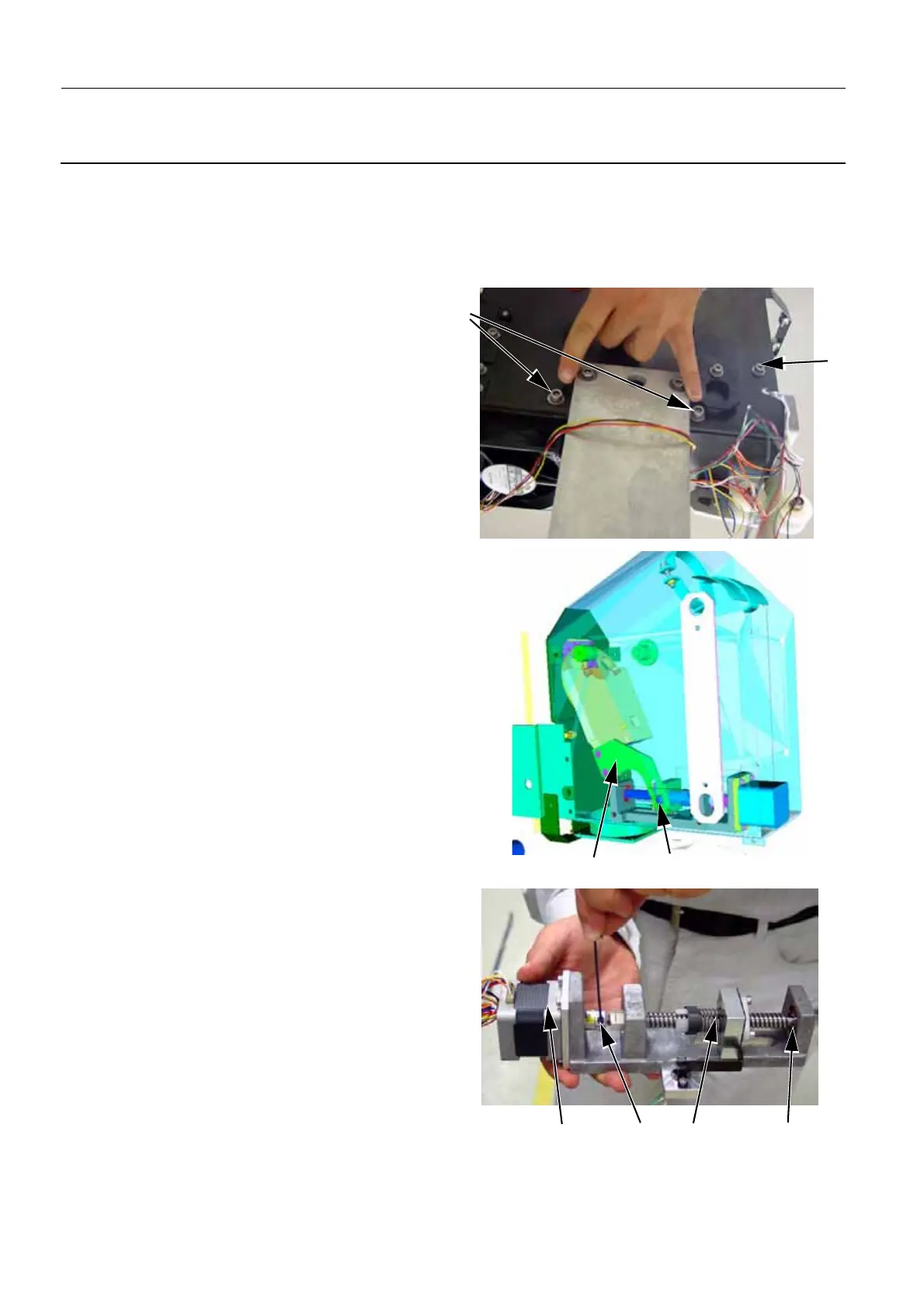
6-1 Disassembly of the Tilt Motor and Drive Assembly
To remove the assembly:
1. Unplug the Tilt motor cable (W404) from the tilt
board (connector J3).
2. Unplug the Tilt sensor cable (W405) from the
tilt board (connector J12).
3. Remove the four screws (2) securing the
upper spacer (4 mm allen wrench).
4. Remove the two screws (3) securing the Tilt
Motor assembly (5 mm allen wrench).
5. Tilt the assembly manually from top to extract
the coupling pin (4) from its fork (5) and remove
the assembly.
If it is not necessary to change components within
the assembly, the procedure is complete.
To remove components from the assembly:
1. Release the motor coupling screw (6) (1.5 mm
allen wrench)
2. Remove the four screws (7) securing the motor
(2.5 mm allen wrench).
3. Remove the Tilt Motor with half of the coupling.
4. If changing the motor, loosen the screw securing
the coupling to the motor (1.5 mm allen wrench)
and remove the coupling.
5. Remove the Tilt Drive Assembly (8) and Tilt Drive
Bearing (9) if necessary.
2
3
4
5
67
8 9

 Loading...


