GE Healthcare Senographe DS
Revision 1 Service Information and Procedures Class A 2385072-16-8EN
Job Card D/R A321 - IDC Computer
Page no. 1511 Chapter 9
JC-DR-A-321_DS.fm
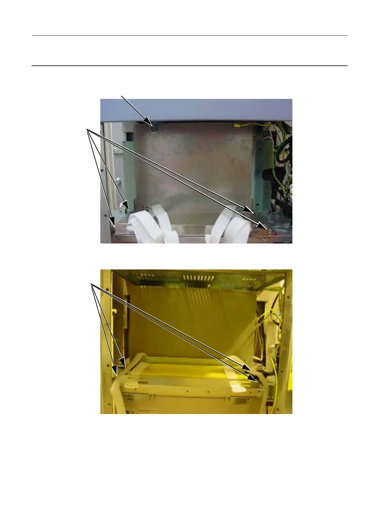
7. If it exists (i.e. on pre-Penduick V3 Control Stations), disconnect the allen screw and bolt (4) connect-
ing the UPS base plate to the L-shaped bracket (2.5 mm allen wrench).
8. Disconnect the four allen screws (5) connecting the UPS base plate to the Control Station framework
(5 mm allen wrench).
9. Remove the UPS base plate from the Control Station frame to expose the IDC Computer.
10. Disconnect all cables from the IDC Computer rear panel.
4
5
5
Pre-Penduick V3 Control Stations
Penduick and above V3 Control Stations and V4 Control Stations

 Loading...


