GE Healthcare Senographe DS
Revision 1 Service Information and Procedures Class A 2385072-16-8EN
Job Card D/R A404 - HV Unit
Page no. 1561 Chapter 9
JC-DR-A-404.fm
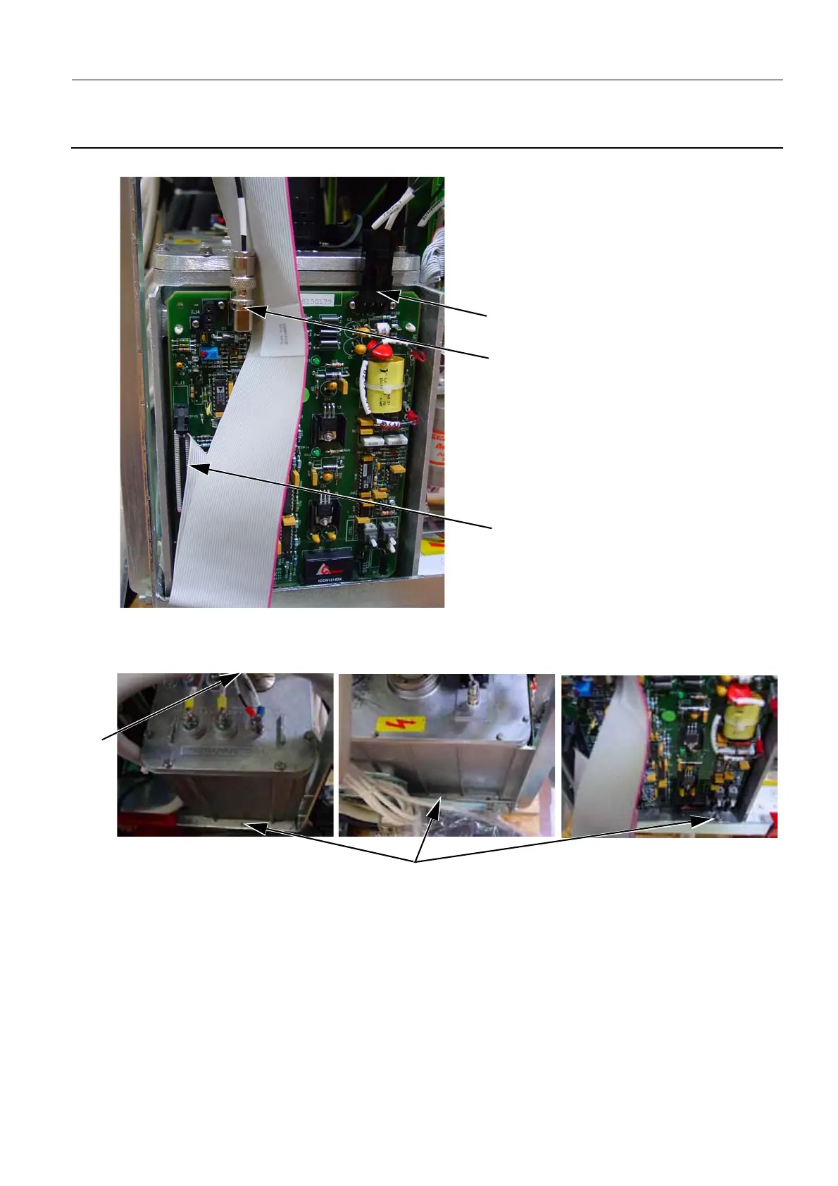
6. On the kV/mA board located on the side of the HV unit, disconnect the cables on XJ2, XJ3, and XJ1.
7. Tighten the air-bleed screw (7).
8. Remove the three allen screws (8) (5 mm allen wrench) that secure the HV unit to the Generator
framework. The three allen screws are located on the three accessible sides of the HV unit.
9. Carefully remove the faulty HV unit from the Generator.
6-2 Installation of the HV Unit
1. Carefully place the new HV unit into the Generator framework. Ensure that the holes for the three
allen screws line up with the three threads on the Generator framework.
2. Attach the three allen screws (1) (5 mm allen wrench) to secure the HV unit to the Generator frame-
XJ1
XJ3
XJ2
8
7

 Loading...


