GE Healthcare Senographe DS
Revision 1 Service Information and Procedures Class A 2385072-16-8EN
Job Card D/R A404 - HV Unit
Page no. 1563 Chapter 9
JC-DR-A-404.fm
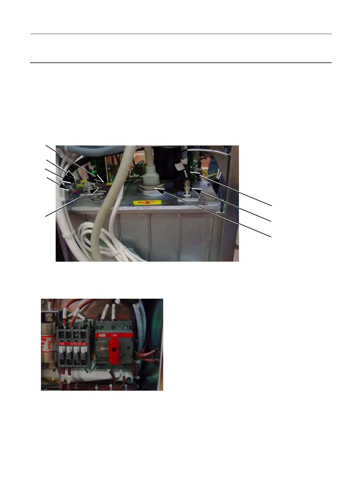
4. On the HT block, disconnect the following, in the sequence listed:
- HT probe cable: GKC (2)
- inverter GKA/1 (3) (8 mm open-ended wrench)
- inverter GKA/2 (4) (8 mm open-ended wrench)
- white and black ground connections (two wires) (5) (8 mm open-ended wrench)
- green ground connection (6) (8 mm open-ended wrench)
- heating/bias connector GKB (7)
- HT connector (8)
5. Grease the HT end-piece if necessary.
6. Slacken the air-bleed screw (9).
7. Switch on the electrical power supply, both from the Mains Distribution Panel in the room and on the
rotary switch in the Generator cabinet (position I).
8. Switch on the Senographe system electrical power (i.e. Generator, Gantry, and Control Station).
9. Wait until the Gantry boot is complete, and check that no error has been reported.
If the HV unit is operating correctly, the LED states on the kV/mA board are as follows:
• all three of the green LEDs (i.e. DS1, DS2, and DS3) are ON
10. Reinstall the Generator covers (see Job Card PHY A042 - Remove/Reinstall Generator Covers on
page 513).
8
7
2
6
5
3
9
4

 Loading...


