GE Healthcare Senographe DS
Revision 1 Service Information and Procedures Class A 2385072-16-8EN
Job Card D/R A406 - Generator Command Board 400-PL1
Page no. 1573 Chapter 9
JC-DR-A-406.fm
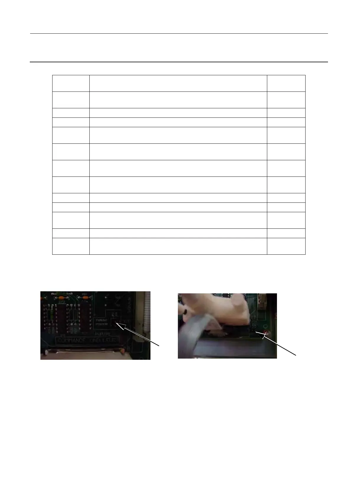
4. Ensure that the JP3 and JP4 (2) jumpers and JP1 and JP2 (3) above and below the XJ8 connector
on the Generator Command board are set the same as the defective board that you have just
replaced.These jumpers determine the room lamps and door configuration, which can vary one each
customer site.
5. If the customer wants a different lamp and door configuration to before, set jumpers JP1 and JP2 as
required according to the table below. Place unused jumpers in the parking positions JP3 and JP4.
Note:
If there is no door switch, jumpers JP1 and JP2 must both be present (case 4 in the table).
Connector
Label
Description of cable
(usually identified by code on a white label)
Cable color
XJ1 400 PL1 XJ1
(red line on right of ribbon connector)
Gray
XJ2 XJ2 Black
XJ3 400 PL1 XJ3 Black
XJ4 400 PL1 XJ4 5 Black
1 White
XJ5 C801418 XP1 XP2
(ribbon cable to kVmA board, red line on right of ribbon connector)
Gray
XJ6 400 PL1 XJ6
(red line on right of ribbon connector)
Gray
XJ7 400 PL1 XJ7
(red line on top of ribbon connector)
Gray
XJ8 The X-ray Console cable White
XJ9 45440115 Black
XJ10 400 PL2 XJ2, 45440116, 400 PL1 X10
(red line on top of ribbon connector)
Gray
XJ12 Empty N/A
XJ13 400 PL1 XJ13
(red line on left of ribbon connector)
Gray
2
3

 Loading...


