GE Healthcare Senographe DS
Revision 1 Service Information and Procedures Class A 2385072-16-8EN
Job Card CAL A011 - Calibration of kV Scale Factor
Page no. 1669 Chapter 9
JC-CAL-A-011.fm
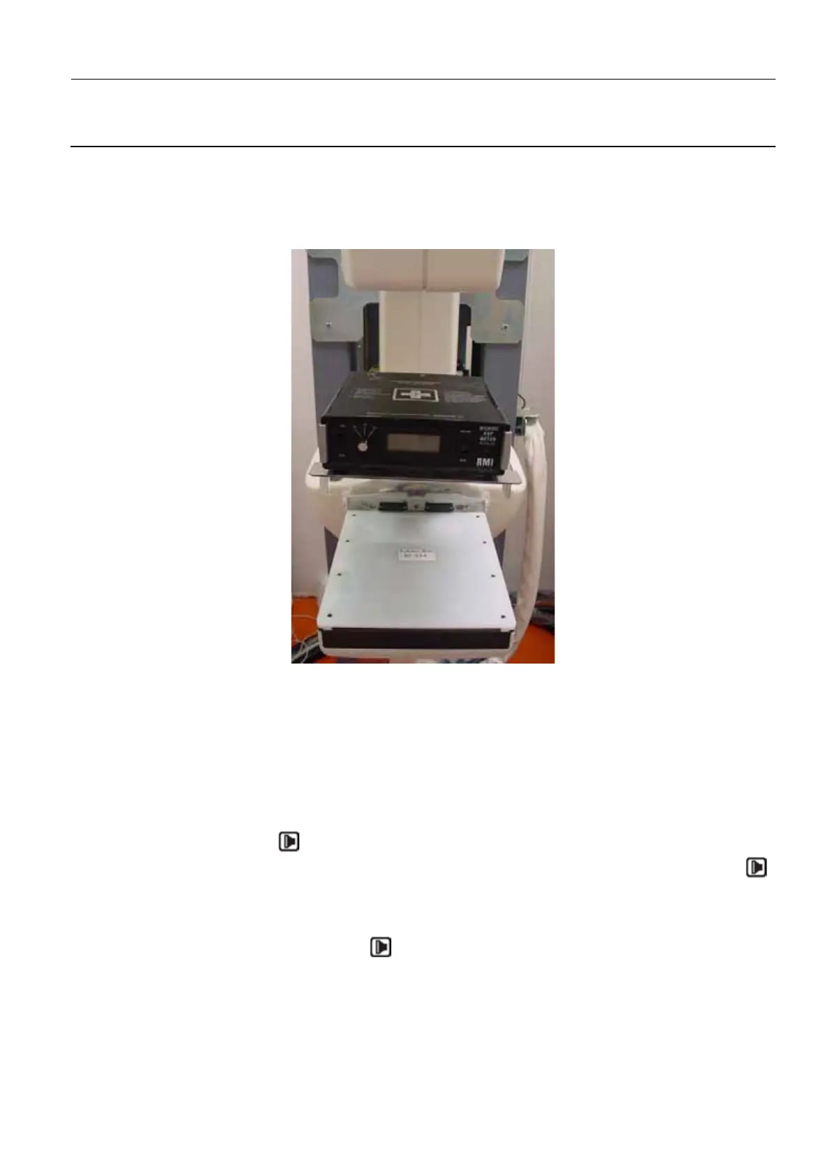
The purpose here is simply to reduce the distance between the kV peak meter and the X-ray source
- see applicable documentation for minimum acceptable distance from X-ray source, if any.
4. Place the kV peak meter on the Radiation Protection Plate located on the Standard 19 X 23 Com-
pression Paddle. Turn it on and set it to the MO/MO position. Set the waveform selector to CP (con-
stant potential), for RadCal 4082 turn it by using the "Normal" button.
5. Use the Senographe light centering device to center the kV peak meter target with the X-ray zone.
6. Select manual exposure mode, and set the X-ray parameters to:
Mo track/Mo filter, 50 mAs, LF
6-2 Perform the calibration procedure
1. Select SETUP/GENE/INSTAL/GENE/GENE/KV/CALIB/1st pt/CALIB on the X-ray Console.
Note:
By default, the kV command value sent by the software for this 1st point is 25 kV.
2. Press the Exposure button on the X-ray Console and hold it down. A single 1-second exposure is
taken. CALIBRATION END appears on the X-ray Console display. Release the Exposure button .
Note down the kV value displayed on the kV peak meter.
Note:
If for some reason this exposure has to be repeated, select SETUP/CALIB on the X-ray Console
before pressing the Exposure button again.
3. Select SETUP/kV_M on the X-ray Console. Enter the kV value read from the kV peak meter by using
the NEXT and VALID keys and rotating the kV dial. If necessary (for example with the RMI 232 vVp
meter) remember to apply the kV correction value from the meter’s calibration curve to the value dis-
played on the kVp meter. For more information on specifying numeric values on the X-ray Console
refer to Representation of Numeric Parameters on page 96.

 Loading...


