Chapter 9 Page no. 1688
JC-CAL-A-031.fm
GE Healthcare Senographe DS
Revision 1 Service Information and Procedures Class A 2385072-16-8EN
Job Card CAL A031 - Lift Calibration
The numbered circles 1, 2, 3 and 4 correspond to the procedural sections within this Job Card as follows:
1. 6-2-1, Upper Optical Fork Positioning (if the ceiling height has changed in the room)
2. 6-2-2, Lower Limit Adjustment (Lift Potentiometer Lower Reference Voltage at 0 mm)
3. 6-2-3, Upper Limit Adjustment (Lift Potentiometer Upper Reference Voltage at 650 mm)
4. 6-2-4, Selection of the Lift Travel Limit (completion)
The top of the Senographe system Tube Head can travel up to three different discrete maximum heights,
corresponding to each of the three different lift travel limits. Assuming you have accurately set the lower
lift travel limit to 670 ±2 mm from the floor, the corresponding maximum Tube Head heights and mini-
mum required ceiling for each of the three different Lift Travel Limits are as follows.
Goal of Calibration:
• If the ceiling height has changed, then select the upper optical fork position to an appropriate position
(either top, middle or bottom) in order to avoid collision with the ceiling.
• Calibrate the Lift Potentiometer.
• Set the lift lower limit and the lift travel limit in software, defining the minimum and maximum usable
heights.
• Calibration is necessary to set the lift lower and upper travel limits in software, defining the minimum
and maximum usable heights.
- The lower limit is set at a pre-determined minimum usable height to establish a reference point for
the measurement system (potentiometer and encoder).
- The upper limit is then set at the maximum usable height. This may be the maximum attainable by
the system, or may be limited to avoid collision with the room ceiling.
• When the limits have been set, the system is able to take account of arm rotation while controlling lift
movement to avoid collisions.
• Optical sensors (the "optical forks") are used to recognize and stop any movement beyond the soft-
ware limits, before impact with mechanical stops.
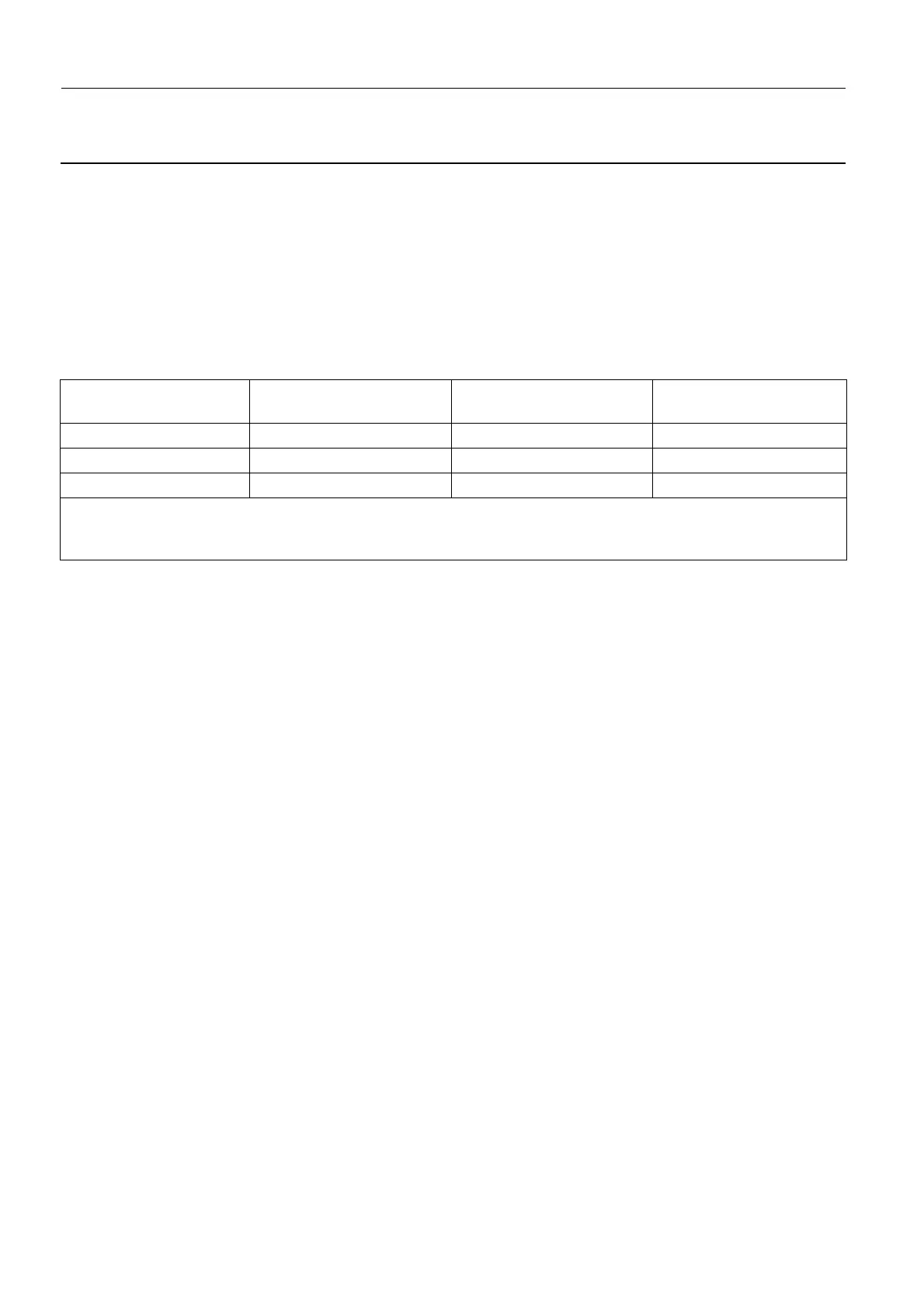
Lift Travel Limit Corresponding Upper
Optical Fork Position
Corresponding Max.
Tube Head Height *
Recommended Min.
Ceiling Height **
650 mm Bottom 2230 mm 2300 mm
750 mm Middle 2330 mm 2400 mm
850 mm (default setting) Top (default setting) 2430 mm 2500 mm
* - Assumes that the lower lift travel limit is accurately set.
** - The recommended minimum ceiling height assumes that there is a marginal gap of 70 mm between the top of
the Tube Head and the ceiling.

 Loading...


