Chapter 3 Page no. 296
Indicators and Switches.fm
GE Healthcare Senographe DS
Revision 1 Service Information and Procedures Class A 2385072-16-8EN
Central Listing
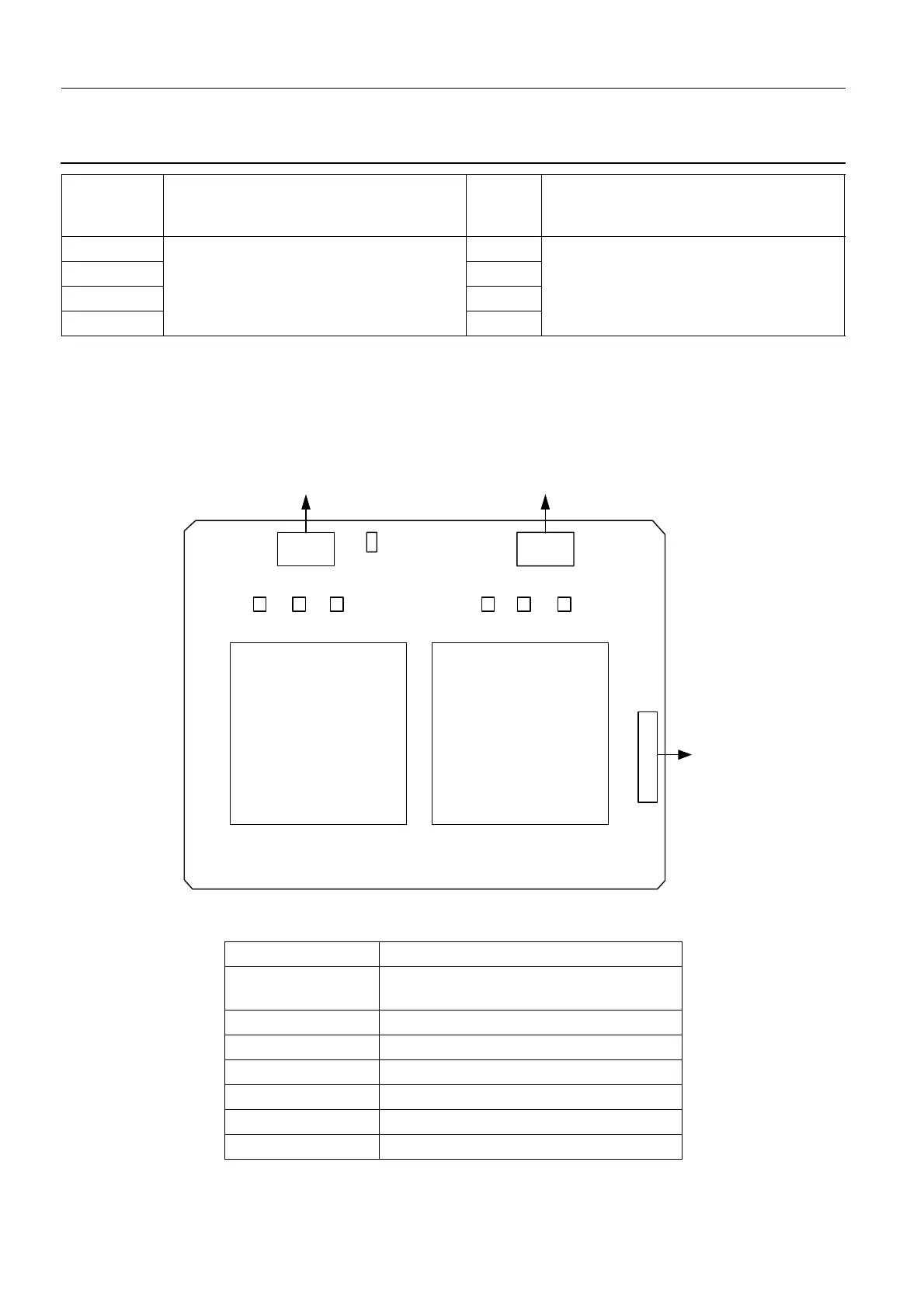
4-7. DC-DC Board PL402 (Collimator Supply)
DS6 3.3 V Green ON when the 3.3 V supply voltage is OK
OFF when the 3.3 V supply voltage is
defective
DS7
Error indicators
Not used - for future application
Red
Error indicators
Not used - for future application
DS8 Red
DS9 Red
DS10 Red
Jumper/Test Point Function
TP1 Jumper present: Lamp ON (test)
Jumper absent: Normal setting
TP2 Trim (not used)
TP3 Gnd (24 V)
TP4 24 V
TP5 Trim (not used)
TP6 Gnd (12 V)
TP7 12 V
• Board-Collimator DC-DC PL402; see component index page 157 .
J5
TP1
J3
ToLight
J4
ToControlBoard
TP4 TP2 TP3 TP7 TP5 TP6
48V