GE Healthcare Senographe DS
Revision 1 Service Information and Procedures Class A 2385072-16-8EN
Job Card ELE A028 - Collimation Checks
Page no. 685 Chapter 7
JC-ELE-A-028.fm
In order to complete the tables above and the tables in the Action limits section, perform the following
steps for each edge of the field (each XR-M film strip) for both Mo and Rh anode tracks, and if necessary
for all field offset positions.
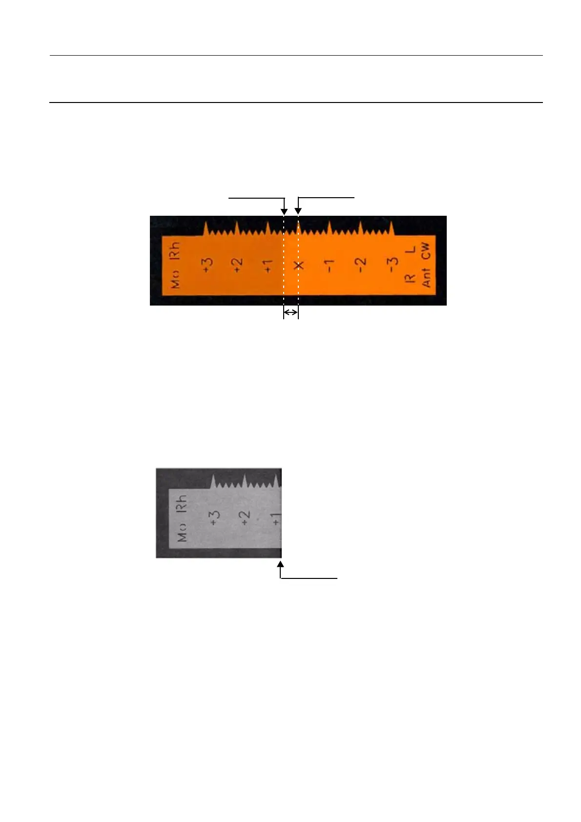
1. Directly from the XR-M film strip, determine the deviation Y
f
, between the X-ray field and the light field
in the plane of the film. Y
f
can be directly read from the incorprated ruler on the XR-M film strip. In
the example illustration below, Y
f
is 5 mm.
Note:
On the XR-M film strip, the distance between the major "teeth" of the saw tooth pattern is 10 mm,
and the tooth-to-tooth distance is 2 mm.
Insert the measured value of Y
f
in the tables above and in the tables for action limit 1 on page 690.
2. Determine the deviation Z
f
, between the X-ray field from the edge of the detector in the plane of the
film. To determine the deviation Z
f
, proceed as follows:
a. From the RAW digital image in the AWS, view the digital image of the XR-M film strip, and deter-
mine the location of the detector edge (D) based on the extent of the XR-M film strip imaged. In
the example image below, the edge of the detector (D) is 9 mm from the "X" reference marker.
Insert the determined value of D in the tables above.
b. Knowing the location of the x-ray field edge from step 1 above (i.e. Y
f
), determine the deviation of
the x-ray field edge from the detector edge in the plane of the film (Z
f
) by using the following equa-
tion:
Z
f
= D - Y
f
Eq. 1
For this example, the edge of the x-ray field is 5 mm from the "X" and the edge of the detector is
9 mm from the "X", and hence, Z
f
is 4 mm. The relative positions of the edges of the light field, x-
ray field, and detector become more apparent when the x-ray image is scaled and superimposed
on the film strip as illustrated in the example below.
Edge of light field
(in the plane of the film)
Edge of X-ray field
(in the plane of the film)
Y
f
= deviation between X-ray field and light field in the plane of the film
Edge of detector