App1-14 Appendix 1 PLC2Way
Data Sampling in the PLC2 Memory
To perform data sampling in the PLC2 memory, the following settings are required.
• Temperature control network/PLC2Way table editing (Refer to page App1-10.)
• Buffering area setting
• Memory card setting (when [SRAM] or [CF Card] is selected for [Store Target] in the [Buffering
Area Setting] dialog)
• Trend sampling or data sampling setting (setting for displaying data stored in the specified buffer)
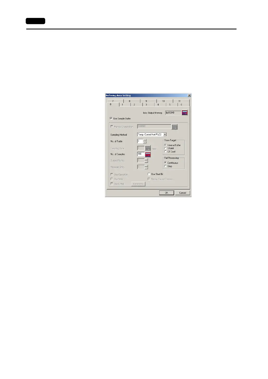
1. Buffering area setting
Click [System Setting] → [Buffering Area Setting]. The [Buffering Area Setting] dialog is opened.
[Sampling Method]
Temperature Control Net/PLC2
[No. of Table]
Select the temperature control network/PLC2Way table number for sampling.
[No. of Samples]
Specify the number of sampling times.
[Store Target] (Internal Buffer/SRAM/CF Card)
Choose the desired medium for storing sampling data.
- Internal Buffer: Stores data in the internal buffer of the V7 series. (RAM)
- SRAM: Stores data in the SRAM area.
(SRAM mounted on the unit, V7EM-S, REC-MCARD SRAM)
- CF Card: Stores data in the CF card.
[Full Processing] (Continuous/Stop)
Choose the desired processing when the target medium space has been used up.
- Continuous: When [No. of Samples] has been exceeded, data from the oldest is
discarded.
- Stop: When [No. of Samples] has been exceeded, sampling is stopped.
• Calculating the buffering area capacity
When [Internal Buffer] is selected for [Store Target] in the [Buffering Area Setting], the maximum
available capacity is 32k words.
When [Temp Control Net/PLC2] is selected for [Sampling Method], the required capacity can be
calculated as shown below.
1 sample = [Words*] + 2 words
Buffer size = [No. of Samples] × 1 sample
* [Words] here means the number of words in the memory addresses used in the temperature
control network/PLC2Way table that is set for [No. of Table].