App6-16 Appendix 6 Universal Serial Communications
• Read Area
This memory area is necessary when the display screen is changed by a command received from
the host. Be sure to allocate only $u memory. Address allocation is shown in the table below. For
details on addresses, refer to Chapter 1 in the Reference Manual (Function).
• Write Area
This memory area is used to write information regarding screen number, overlap, and input mode
when the screen display status is changed by a command received from the host. Be sure to
allocate only $u memory.
Address allocation is shown in the table below.
For details on addresses (n + 0 to n + 2), refer to Chapter 1 in the Reference Manual (Function).
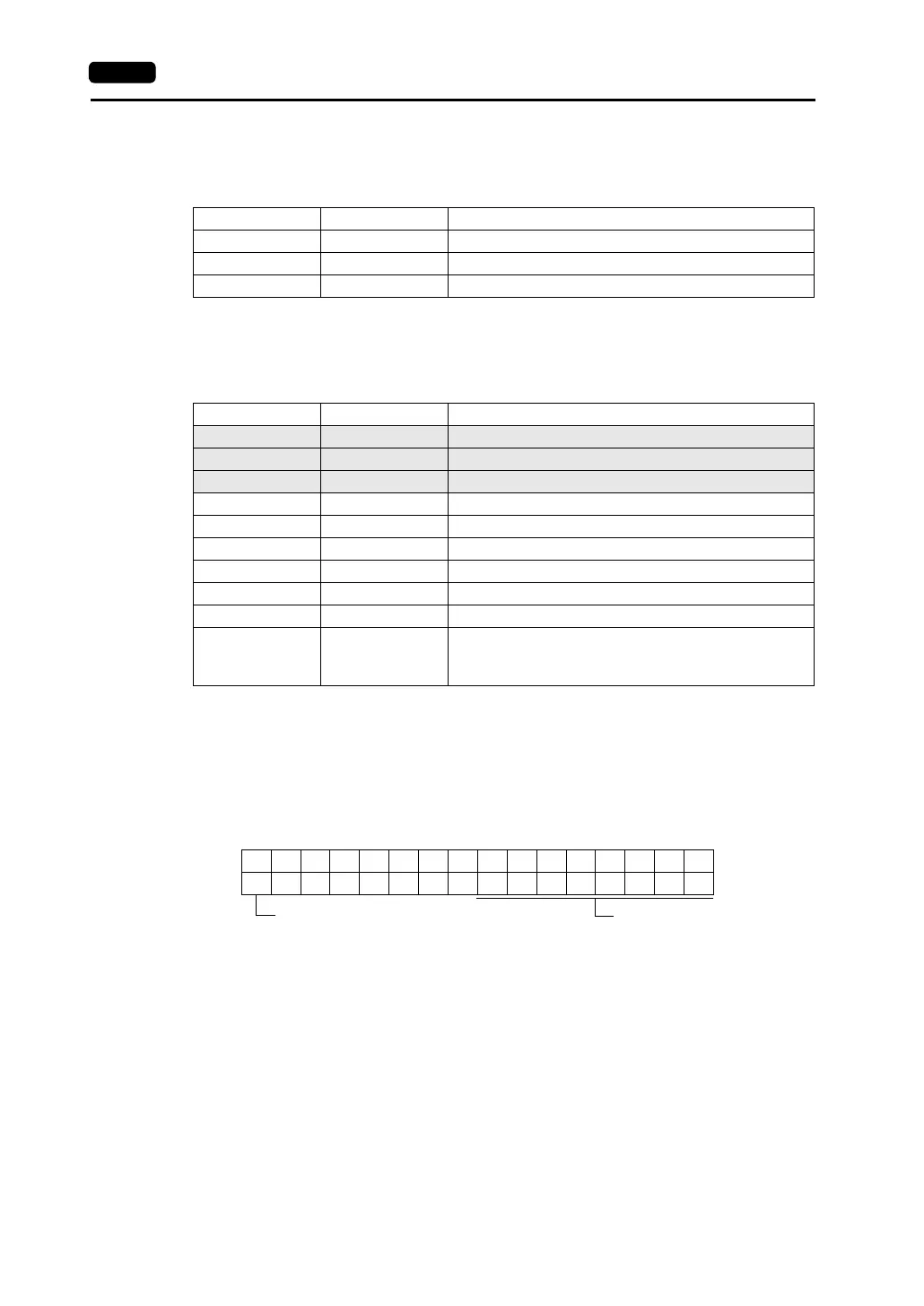
- n + 3 (SW0) switch data No. 0, n + 4 (SW1) switch data No. 1
When the switch output memory is set at an address location from 80 to 95 in the system
memory ($s) of internal memory, the switch number is written on lower 8 bits.
The relationship between the switch number and the bit is shown in the following table. (Refer
to page App6-40.)
Address Name Contents
n + 0 RCVDAT Sub command/data
n + 1 SCRN_COM Screen status command
n + 2 SCRN_No External screen command
Address Name Contents
n+0 CFMDAT Sub command/data
n+1 SCRN_COM Screen status
n+2 SCRN_No Displayed screen
n + 3 SW0 No. 0 switch data
n + 4 SW1 No. 1 switch data
n + 5 ENT0 Entry information 0
n + 6 ENT1 Entry information 1
n + 7 ENT2 Entry information 2
n + 8 GREPNS Global response
n+9
•
•
•
n+15
Reserved (7 words)
15 14 13 12 11 10 09 08 07 06 05 04 03 02 01 00
0000000
n + 3, n + 4 (SW0/SW1)
Switch numberSwitch status
0: OFF
1: ON