496 Programming: Execution of CAM Programs, Multi-axis Machining
12.3 The PLANE function: Tilting the working plane (software option 1)
Input parameters
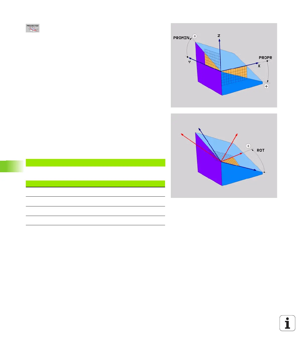
Proj. angle 1st coordinate plane?: Projected angle
of the tilted machining plane in the 1st coordinate
plane of the fixed machine coordinate system (Z/X for
tool axis Z, see figure at top right). Input range: from
-89.9999° to +89.9999°. The 0° axis is the principal
axis of the active working plane (X for tool axis Z. See
figure at top right for positive direction)
Proj. angle 2nd coordinate plane?: Projected angle
in the 2nd coordinate plane of the fixed machine
coordinate system (Y/Z for tool axis Z, see figure at
top right). Input range: from –89.9999° to +89.9999°.
The 0° axis is the minor axis of the active machining
plane (Y for tool axis Z)
ROT angle of the tilted plane?: Rotation of the
tilted coordinate system around the tilted tool axis
(corresponds to a rotation with Cycle 10 ROTATION).
The rotation angle is used to simply specify the
direction of the principal axis of the working plane (X
for tool axis Z, Z for tool axis Y; see figure at bottom
right). Input range: from 0° to +360°.
Continue with the positioning properties (see
"Specifying the positioning behavior of the PLANE
function" on page 506)
NC block
Abbreviations used
5 PLANE PROJECTED PROPR+24 PROMIN+24 ROT+30 .....
Abbreviation Meaning
PROJECTED Projected
PROPR Principal plane
PROMIN Minor plane
ROT Rotation

 Loading...


