6.1 Making manual measurements
80
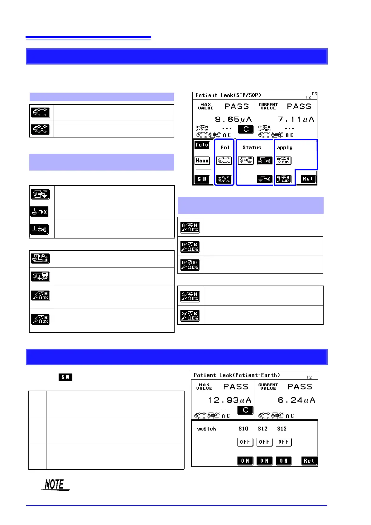
The indication varies depending on the network, class setting, and measurement mode selected.
See Appendix2 "List of instrument status, other test condition and special test condition"
(p. A4)
Changing manual measurement items
1
2
Equipment with an internal power supply cannot be
set.
1. Power supply polarity
Indicates "positive phase."
Indicates "negative phase."
No equipment whose grounding class is internal can
be set.
2. State of equipment under test
(power supply)
Sets "Normal condition."
Sets a "Single fault condition"
(power supply lead is disconnected).
Sets a "Single fault condition"(protective
earth terminal is disconnected).
Other conditions
Sets application of 110% of voltage,
positive phase.
1Sets application of 110% of voltage,
negative phase.
Sets application of 110% of voltage,
positive phase.
(When selecting network B1.)
Sets application of 110% of voltage,
negative phase.
(When selecting network B1.)
3. Other test condition (Other applied voltages)
(When selecting network B2.)
Sets application of 110% of voltage,
positive phase.
Sets application of 110% of voltage,
negative phase.
Sets application of 110% of voltage, OFF.
Special test condition (Specific applied voltage)
Sets application of 110% of voltage,
positive phase.
Sets application of 110% of voltage,
negative phase.
3
*
The "N" key indicates positive phase and "R" nega-
tive phase.
SW status (only network B2 on ST5540)
Pressing in the manual measurement setting
screen opens the switch setting screen.
S10
SW for connecting functional earth terminal and
power supply system for measurement. Set to
On to connect to the LINE IN E terminal.
S12
SW for connecting patient connection to ground
of power supply circuit for measurement. Set to
On to connect to the LINE IN E terminal.
S13
Terminal providing ground connection for metal
accessible part not protectively earthed. Set to
On to connect to the LINE IN E terminal.
For information on connection procedures, refer to (p. 35).
Only manual measurements can be set.