Hardware description 2–53
Hitachi Unified Storage Hardware Service Guide
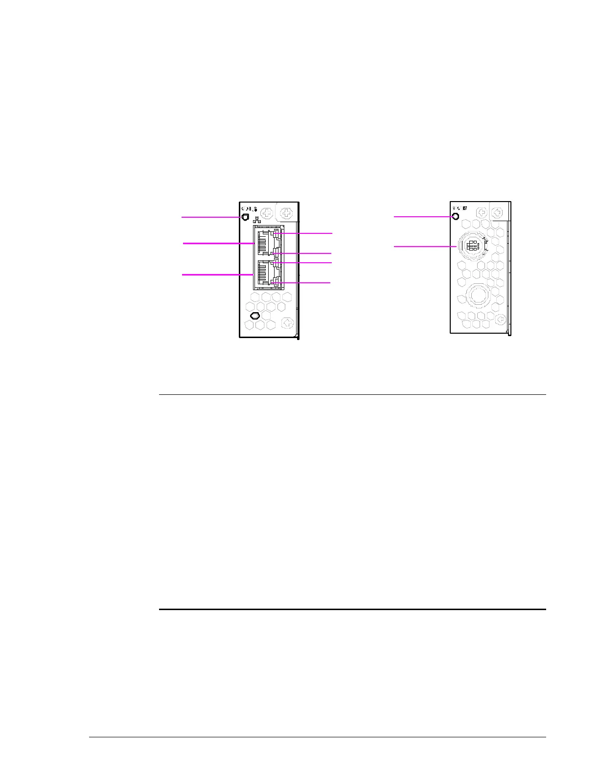
Management Module for CBL/CBLD Controller Box
The Management Module consists of two side-by-side modules. Facing the
back of the CBL/CBLD Controller Box:
• The left module has a status LED, management port, and maintenance
port.
• The right module has a status LED and an uninterruptible power supply
port.
Figure 2-34: CBL/CBLD Management Module
•
Legend Component Color Description
STATUS LED Green ON = power-on status.
Red ON = abnormal operating status. Visit
the HDS Support Portal at
portal.hds.com.
?
ACT LED Yellow ON = data is being transferred.
?
LINK LED Green ON = link status is normal.
?
LAN 0 Maintenance Port
See Maintenance port on page 2-37.
?
LAN 1 Management Port
See Management port on page 2-37.
?
STATUS LED Green ON = power-on status.
?
UPS Connector — Connects to an uninterruptible power
supply. (This connector is not used on
the CBLD Controller.)