2–54 Hardware description
Hitachi Unified Storage Hardware Service Guide
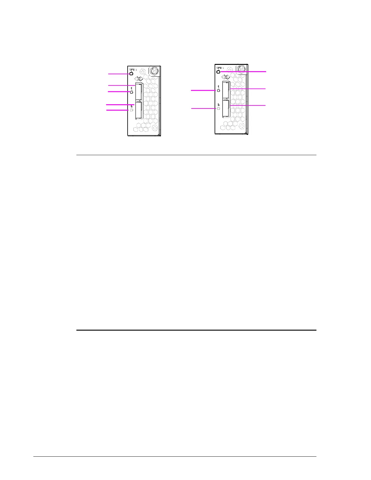
Drive I/O Module for CBL/CBLD Controller Box
The Drive I/O Module consists of two identical modules that each contain a
status LED and two connectors for attaching Drive Boxes.
Figure 2-35: CBL/CBLD Drive I/O Module
Legend Component Color Description
Status LED Green ON = power-on.
Red ON = abnormal operating status. Visit the
HDS Support Portal at portal.hds.com.
?
PATH 3 Drive Box Port Connector for connecting:
• CBL to DBS/DBL/DBF/DBX/DBW.
• CBLD to DBSD/DBLD.
?
PATH 2 Drive Box Port Connector for connecting:
• CBL to DBS/DBL/DBF/DBX/DBW.
• CBLD to DBSD/DBLD.
?
Link/Locate LED Blue ON = Drive Box is connected and link status
is normal.
Orange ON = a Storage Navigator Modular 2 wizard
indicates that a SAS (ENC) cable must to be
inserted into the port.
?
PATH 1 Drive Box Port Connector for connecting:
• CBL to DBS/DBL/DBF/DBX/DBW.
• CBLD to DBSD/DBLD.
?
PATH 0 Drive Box Port Connector for connecting:
• CBL to DBS/DBL/DBF/DBX/DBW.
• CBLD to DBSD/DBLD.