2–6 Hardware description
Hitachi Unified Storage Hardware Service Guide
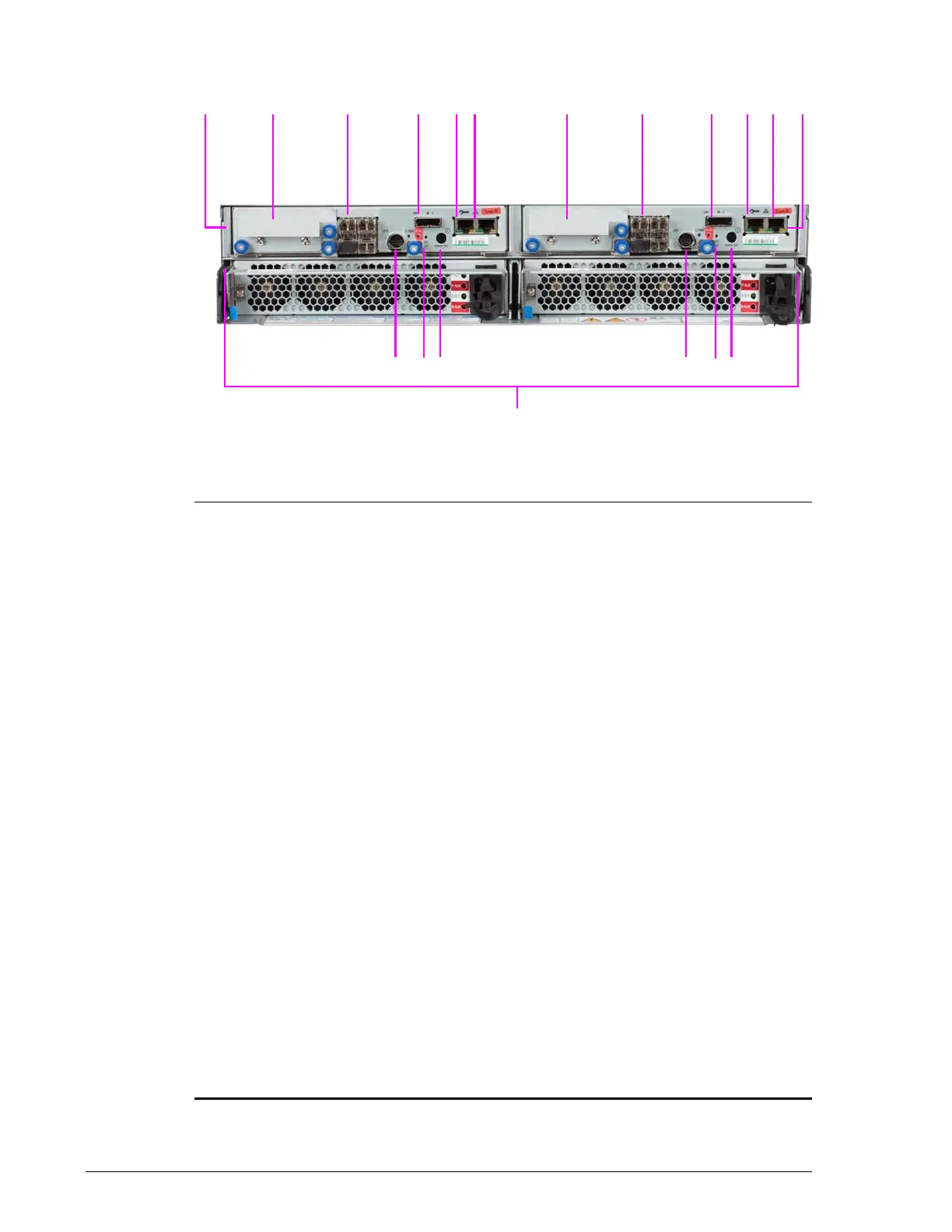
Rear panel
•
Figure 2-4: CBXSS Controller Box rear panel
Legend:
Two Controllers
Controller 0 (left) and Controller 1 (right)
?
Host Interface Option
See Host I/O Boards for CBXSS and CBXSL Controller Boxes on page 2-38.
?
Fibre Channel Ports
See Fibre Channel ports on page 2-35.
?
PATH 0 Expansion Port
Connects to a DBS or DBL Drive Box. Do not connect to a DBX Drive Box.
LED above port shows when a link is made:
• BLUE ON = Drive Box is connected and link status is normal.
• ORANGE ON = a Hitachi Storage Navigator Modular 2 wizard indicates
that a SAS (ENC) cable must to be inserted into the port.
?
LAN 0 Maintenance Port
• Left LED: Link Status (green)
• Right LED: Port Activity (yellow)
See Maintenance port on page 2-37.
?
LAN 1 Management Port
• Left LED: Link Status (green)
• Right LED: Port Activity (yellow)
See Management port on page 2-37.
?
Power Unit
See Power Unit for CBXSS, CBXSL, CBSS, and CBSL Controller Boxes on
page 2-45.
?
Main Switch
Powers the storage system ON and OFF. When power is OFF, turn on power
by holding this switch longer than 1 second. When power is ON, turn off
power by holding this switch longer than 3 seconds.
?
Reset Switch and Controller LEDs
Use the Reset switch only when instructed by Hitachi Support. For LEDs,
see CBXSS/CBXSL controller LEDs on page 2-34.
?
Uninterruptible Power Supply Port