3-20
(3) Remove the connectors from CN4, CN6 and CN7.
(4) Remove the EZJ125 board.
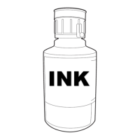
*) At first, remove the fixing screws (2 positions). Then as the drawing below, push the
hook of fixing spacer of EZJ125 board and pull up the EZJ125 board. (Two spacers)
(5) Remove the spacer from EZJ125 board.
*) As the drawing below, push the hook of fixing spacer and pull up the spacer
(Two spacers)
(6) Remove the connectors from CN2, CN3 and CN5.
(7) Replace the EZJ125 board and then install the each part by reversing the above
procedure.
(8) Set up DSW1 and DSW2 according to the nozzle diameter.
(9) Confirm the charging voltage.
(10) Perform the excitation adjustment and the auto phase gain adjustment.
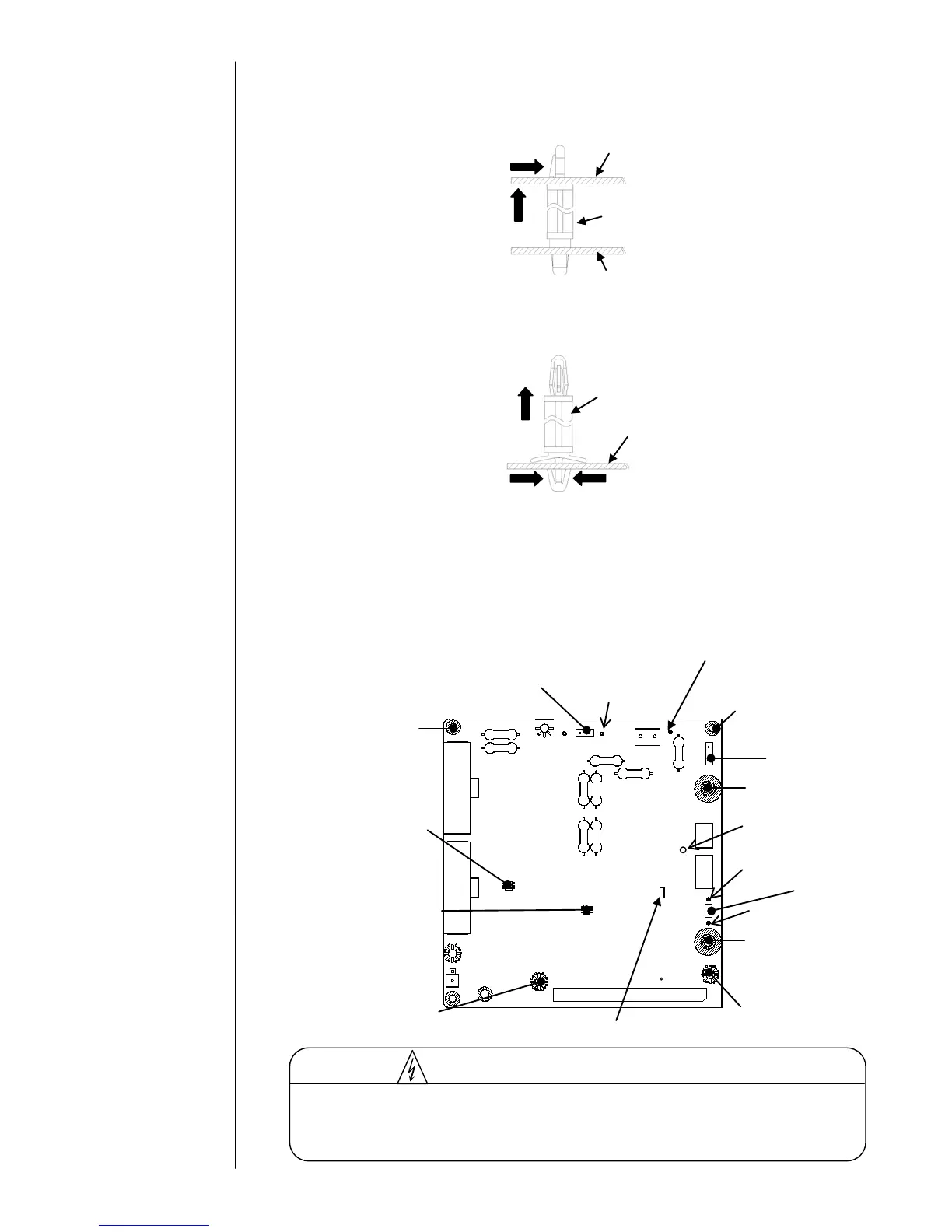
[EZJ125 board external view]
The EZJ125 board has a portion where high voltage is applied. In order to avoid an
electric shock, be sure to turn off the power and wait for at least 10 seconds before
accessing the EZJ125 board.

 Loading...