EasyManua.ls Logo

Hitachi IJ UX - 4 Maintenance of Circulation System; Structure of Circulation System

Hitachi IJ UX
308 pages
To Next Page IconTo Next Page
To Previous Page IconTo Previous Page
Loading...
4-1
4. Maintenance of Circulation System
4.1 Structure of Circulation System
4.1.1 General Structure of Circulation System
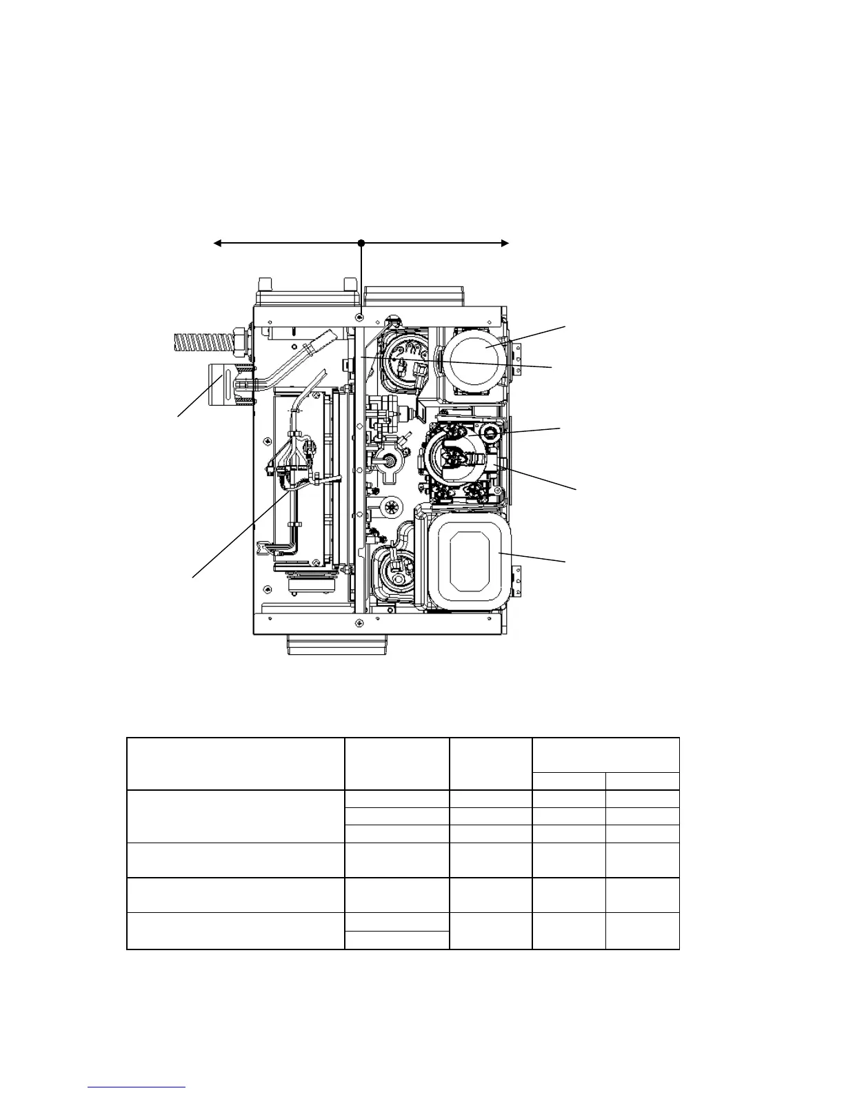
The general structure of the circulation system is shown in the following figure. Using an
open/close type door (unit door) as a partition, the system is roughly divided into an ink
circulating area (the front side of the equipment) and a driving part area (the rear side of
the equipment).
[Caution]
Since the circulation unit is made of plastic, tightening the screws with excessive torque will break the unit.
See the table below for reference torques:
Fixing screw (Part to be fixed)
Parts where
screws are used.
Material
tapped
Reference tightening
torque
N·m
kgf·cm
Self-tapping screw M4X12
(Viscometer, etc.)
Pump unit
PBT(G30)
1.7±0.3
17.3±3
Circulation unit
PBT(G30)
1.7±0.3
17.3±3
Ink main tank
PBT(G30)
1.7±0.3
17.3±3
Self-tapping screw M4X16
(Solenoid valve)
Circulation unit PBT(G30) 1.7±0.3 17.3±3
Self-tapping screw M4X35
(Circulation unit)
Pump unit
ADC12
(aluminum)
1.7±0.3 17.3±3
Self-tapping screw B M3X10
(ICU joint)
Pump unit
PBT(G30) 0.5±0.1 5.1±1
Circulation unit
Ink circulating area
Dri
ving part area
Makeup cartridge
Unit door
Ink filter
Main ink tank
Exhaust duct
Ink cartridge
Pump unit

Table of Contents

Other manuals for Hitachi IJ UX

Related product manuals