5-22
5.13 Head base Replacement Procedure
When damaging the head base, the head base must be replaced. Perform it by the following procedure.
1
Remove the head cover and heater cover.
2
Remove the nozzle described in the item 5.7.
3
Remove the deflecting base described in the item 5.11.
4
Remove the sealing valve described in the item 5.4.
5
Remove the heating unit described in the item 5.5.
6
Remove the gutter base described in the item 5.3.
7
Remove the FG and NH sponges.
8
Remove the fixing screw of the APH sensor board.
9
Unscrew the fastening screw between the head base and the head cable, and remove the head base.
10
Attach a new head base.
「Caution」
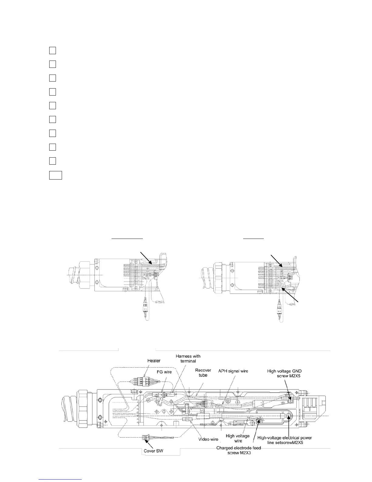
(A) Do not mix up lead wires and tubes which each is disposed on the front face (nozzle side)
and the back face (high voltage cable side).
Front face: UXB,D ink-furnishing tube (E), makeup ink tube (R), circulation tube (J), air purge.
UX-E In addition to the above:Gas supply tube(5)、Liquid recovery tube (6)
Back face: recovery tube, APH boad power supply wire, FG wire, APH signal wire,
video signal wire, heater feeder wire, cover SW signal wire,
EZJ112A board signal wire, high voltage feeder wire

 Loading...