3-44
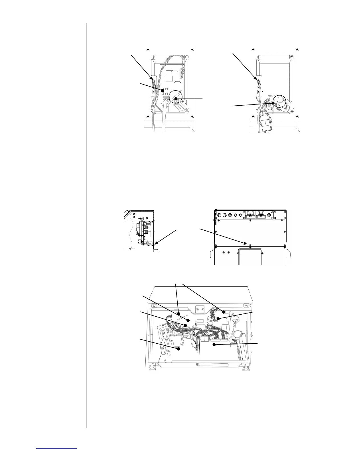
(3) Disconnect the AC input connector of multiple power supply inside the side cover.
(4) Open the maintenance door.
(5) Remove the wire harness from the wire clamp put on the high voltage power supply
protective cover.
(6) Remove the protective cover of high voltage power supply and then remove the
high voltage power supply.
(7) Remove the wire harness from the wire clamp put on the multiple power supply flame.
(8) Remove the fixing screw of back cover.
(9) Remove the two fixing hexagonal spacers and then remove the multiple power supply.
[NOTE] Since the multiple power supply is stuck on the back cover with
double-stick tape, strong power may be needed in the case of removal.
(10)Remove the connector CN2 and 4 of multiple power supply.
(11)Install a new multiple power supply by reversing the above procedure.
Check the clamping position of wire harness and connection of connectors on EZJ126
board (CN11-14, 20-22, 24).

 Loading...