E1 Series Servo Drive User Manual Specification
4-10 HIWIN MIKROSYSTEM CORP.
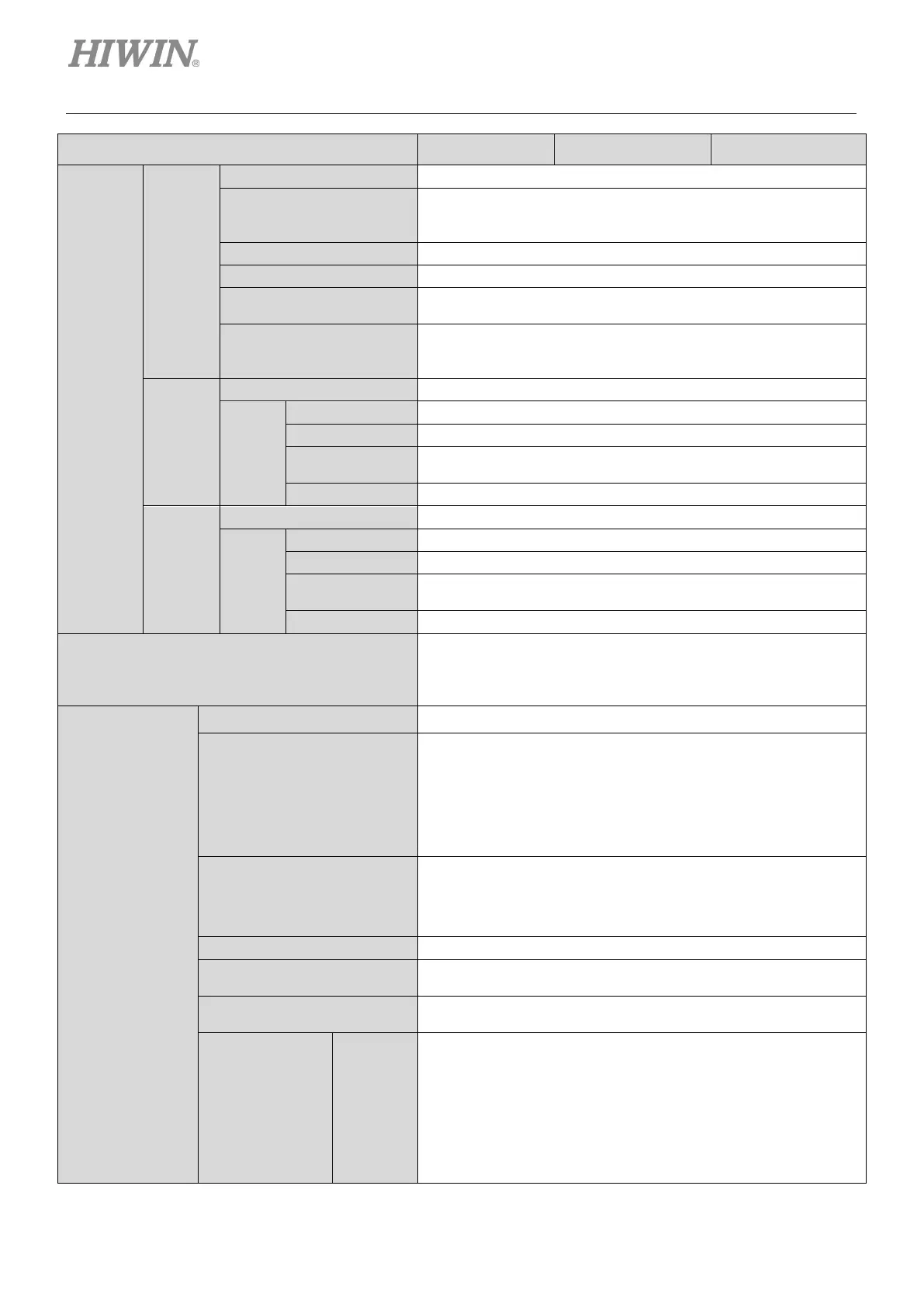
Rated Output 400 W 1 KW 2 KW
Control
Function
Position
Mode
Pulse command from controller
Signal Type
CW/CCW
High-speed optical coupler
Input Signal Differential input or single-ended input
Differential: 5 Mpps
Single-ended: 200 kpps
Electronic Gear
Gear ratio: pulses/counts
Pulses: 1~1,073,741,824
Velocity
Mode
DC voltage command from controller
Analog
Input
100 Hz
16 bit A/D input (V-REF+/-)
Torque
Mode
DC voltage command from controller
Analog
Input
Impedance 14K Ohm
100 Hz
16 bit A/D input (T-REF+/-)
Control Mode
2. Velocity mode
3. Torque mode
4. Full-closed loop mode (Dual loop mode)
Encoder
Feedback
Power Supply +5.1 Vdc±5%, 400 mA
Signal Format
Serial signal
Resolution: 23 bit (Single-turn/multi-turn absolute encoder)
Bandwidth: 5 MHz
Incremental signal
AqB and Z-phase signals (Digital differential TTL signal)
The maximum input bandwidth of each phase is 5 MHz.
Safety Function
Encoder power malfunction detection
Short circuit protection
Undervoltage protection
Overvoltage protection
-2,147,483,648~2,147,483,647 (32 bit)
Maximum Bandwidth of
Differential Input
Quadruple frequency, 20 M counts/s
Linear Motor/Direct Drive
Motor
Depending on encoder type, Excellent Smart Cube (ESC) may
be required.
Emulated
Encoder Output
Z Phase
1. Serial encoder and digital encoder (AqB) are supported.
2. The width of output signal can be adjusted by parameter.
3. Differential signal output
4. Z-phase open collector output is supported.
5. Two output methods can be selected.
Only outputs one Z-phase signal for total travel distance.
Outputs one Z-phase signal per one revolution.

 Loading...


