E1 Series Servo Drive User Manual Electrical Planning
5-28 HIWIN MIKROSYSTEM CORP.
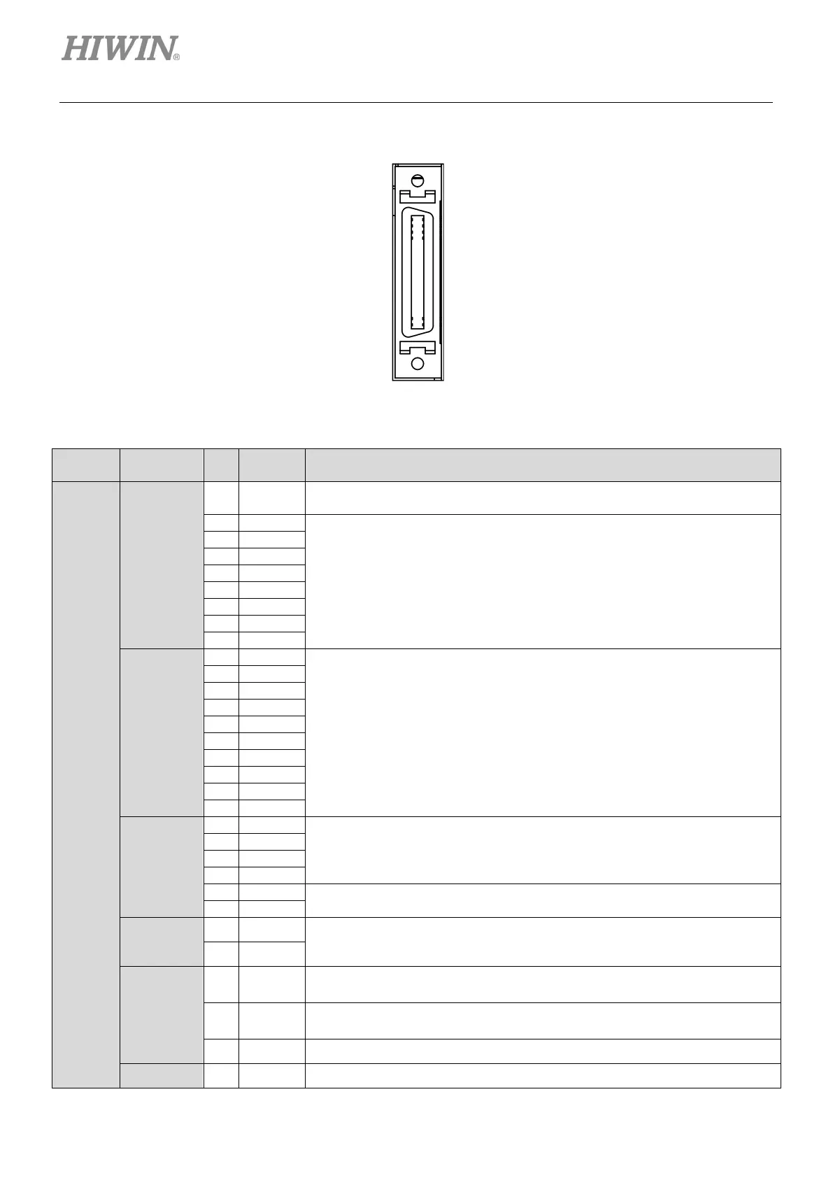
E1 series servo drive (CN6)-Fieldbus
Figure5.5.1.2 Pin definition of CN6-Fieldbus
Table5.5.1.2 Pin definition of CN6-Fieldbus
Category Pin Signal Function Description
Fieldbus
Model
Digital
Input
30 COM
Common point for digital signal inputs
The wiring for digital signals must be sink or source type.
General-purpose input signals
Users are allowed to use the default setting in each control mode or
configure input functions by themselves, please refer to section 8.1.1.
Digital
Output
General-purpose output signals
Users are allowed to use the default setting in each control mode or
configure output functions by themselves, please refer to section 8.1.2.
Encoder
Output
Outputs pulse signals (Pulse type: AqB) according to the setting for
encoder output. For more information of encoder output setting, please
refer to section 8.6.
Outputs one Z-phase signal per one revolution.
Special
Application
9 PT+
For the wiring for position trigger output function, please refer to section
5.5.3. Use Pt00E=t.X to enable or disable position trigger output
10 PT-
Analog
Output
21 AO1
Analog output (+/-10 V)
Monitors motor torque.
22 AO2
Analog output (+/-10 V)
Monitors motor velocity.
23 AOGND Analog signal ground
Ground 35 SG Signal ground
.
.
.
.
.
.
.
18
.
.
.
.
.
.
.
36

 Loading...


