FUEL SYSTEM (PGM-FI)
5-95
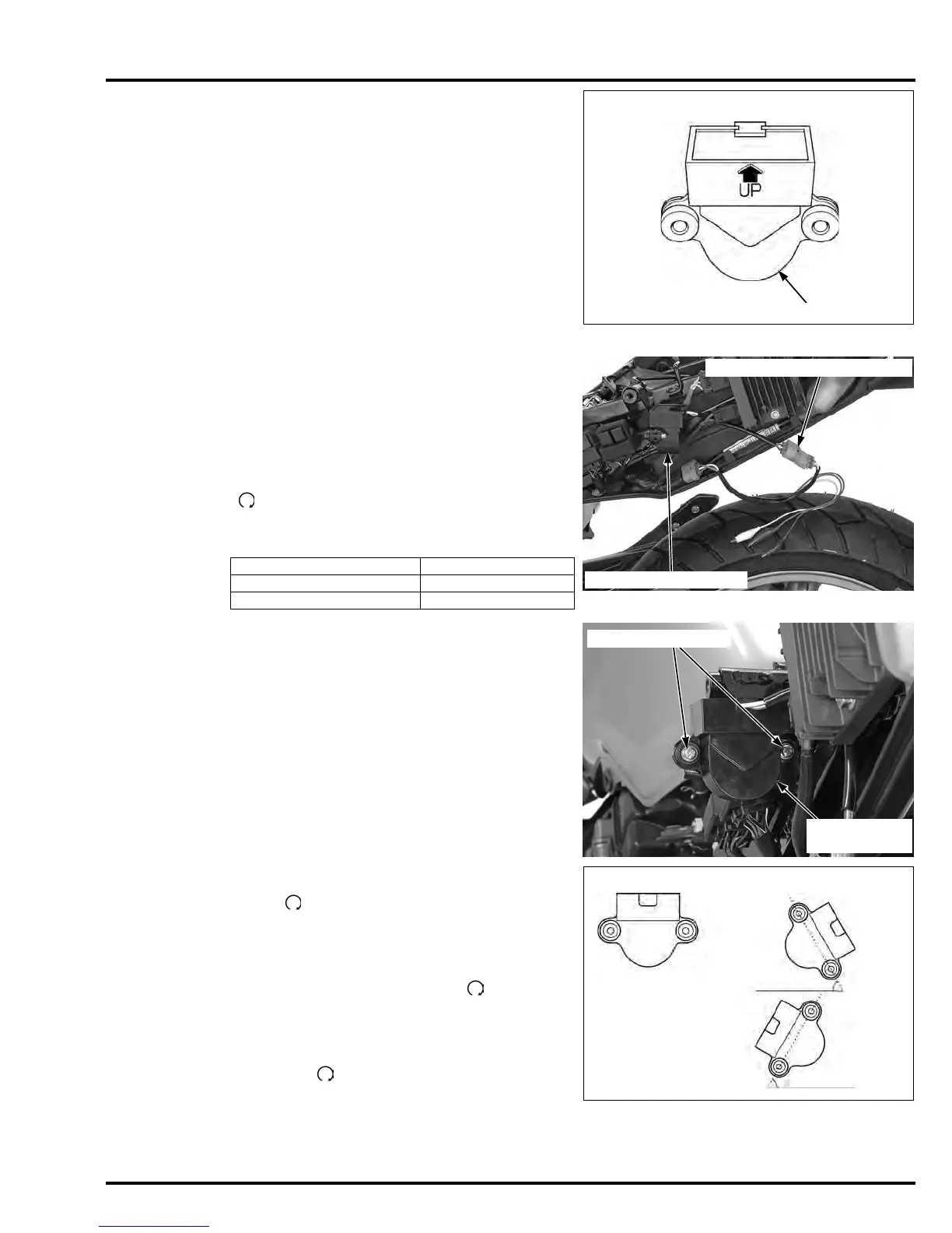
Install the bank
angle sensor with
its “UP” mark
facing up.
Installation is in the reverse order of removal.
Tighten the mounting screws securely.
INSPECTION
Remove the seat (page 2-4).
Disconnect the bank angle sensor 3P (Green) con-
nector and connect the special tool between the
connectors.
Turn the ignition switch ON and engine stop switch
"".
Measure the voltage between the following termi-
nals of the test harness.
Turn the ignition switch OFF and remove the inspec-
tion test harness.
Connect the bank angle sensor 3P (Green) connec-
tor.
Remove the screws, washers and the bank angle
sensor.
Place the bank angle sensor horizontal as shown,
and turn the ignition switch ON and engine stop
switch " ".
The bank angle sensor is normal if the engine stop
relay clicks and power supply is closed.
Incline the bank angel sensor approximately 60
degrees to the left or right with keeping the ignition
switch ON and engine stop switch " ".
The bank angle sensor is normal if the engine stop
relay clicks and power supply is open.
If you repeat this test, first turn the ignition switch
OFF, then turn the ignition switch ON and engine
stop switch " ".
TOOL:
Inspection test harness 07GMJ-ML80100
TERMINAL STANDARD
White clip (+) – Red clip (–) Battery voltage
Green clip (+) – Red clip (–)0 – 1 V
INSPECTION TEST HARNESS
BANK ANGLE SENSOR
BANK ANGLE
SENSOR
SCREWS/WASHERS
60° BANK ANGLE POSITION
(approximately) 60°
NORMAL
POSITION
60° (approximately)
Manuals by Motomatrix / www.motomatrix.co.uk / The Solution For Lost Motorcycle Coded Keys.
email: info@motomatrix.co.uk


 To Next Page