LIGHTS/METERS/SWITCHES
20-23
SPEEDOMETER/VS SENSOR
SYSTEM INSPECTION
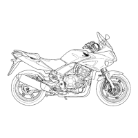
CBF600S/SA:
Check that the indicators function properly.
• If they do not function, perform the power and
ground line inspection of the combination meter
(page 20-21).
• If they function, shift the transmission into neu-
tral, the combination meter 16P (Black) connec-
tors are connected and turn the ignition switch
ON.
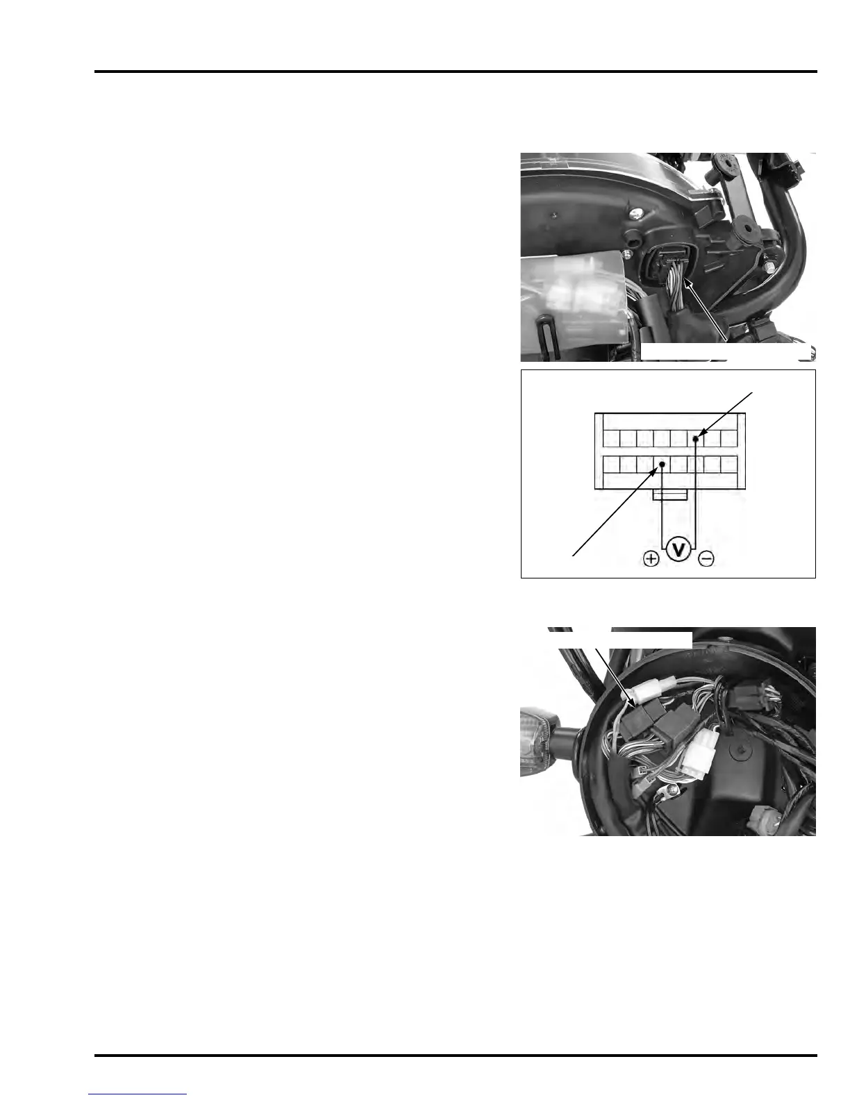
Measure the voltage between the Pink/blue (+) and
Green/black (–) wire terminals of the 16P (Black)
connector.
Slowly turn the rear wheel by hand.
There should be 0 to 5 V pulse voltage.
– If pulse voltage appears, replace the speedome-
ter (page 20-16).
– If pulse voltage does not appear, check for open
or short circuit in Pink/Green wire.
If the Pink/Green wire is OK, check for the vehicle
speed sensor (page 20-24).
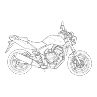
CBF600N/NA:
Check that the indicators function properly.
• If they do not function, perform the power and
ground line inspection of the combination meter
(page 20-21).
• If they function, shift the transmission into neu-
tral, the combination meter 6P (Natural) and 9P
(Black) connectors are connected and turn the
ignition switch ON.
Viewed from harness side/
the 16P connector:
Pink/blue
Green/black
Manuals by Motomatrix / www.motomatrix.co.uk / The Solution For Lost Motorcycle Coded Keys.
email: info@motomatrix.co.uk


 To Next Page