EasyManua.ls Logo

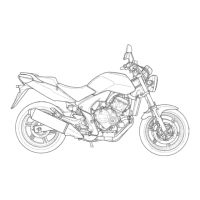
Honda CBF600SA - Abs System Diagram

Honda CBF600SA
620 pages
Print Icon
To Next Page IconTo Next Page
To Previous Page IconTo Previous Page
Loading...
ANTI–LOCK BRAKE SYSTEM (ABS; CBF600SA/NA)
16-3
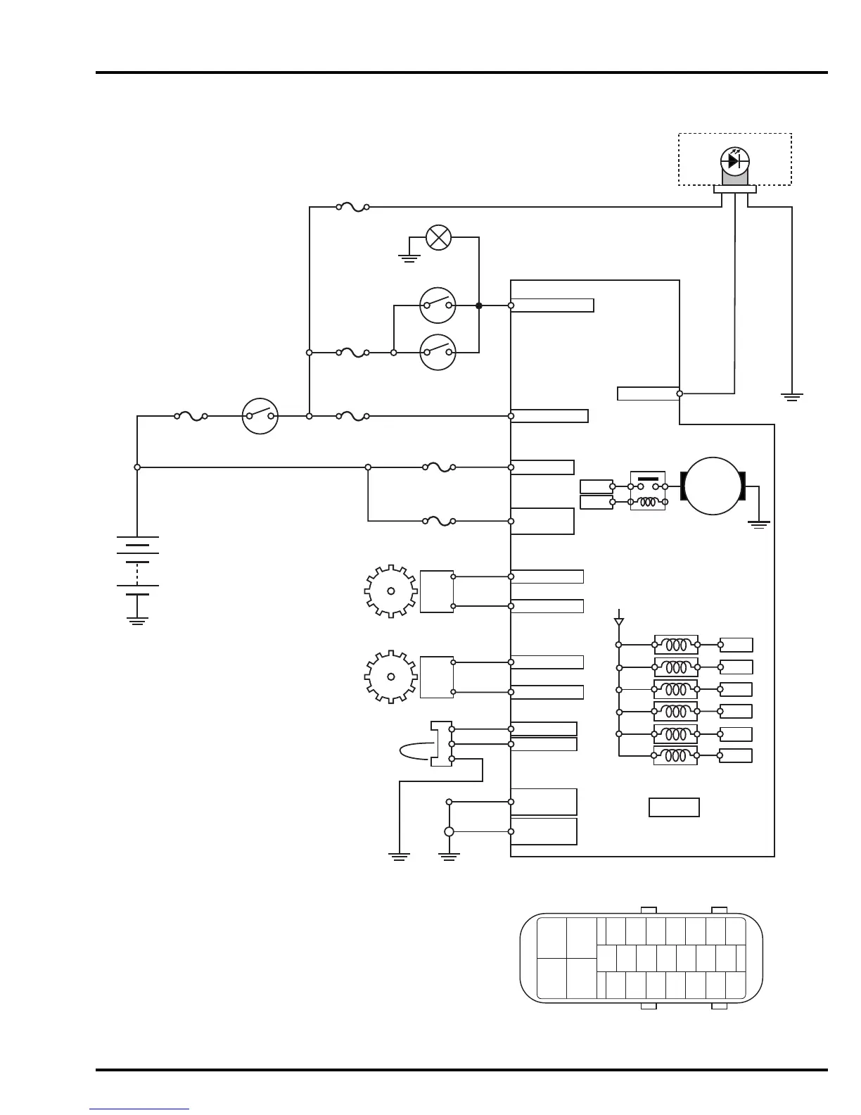
ABS SYSTEM DIAGRAM
G/Y
Bl/G Bl/G
Brake
Switches
Brake Light
O/Bu
P/W
G/R
Y/Bl
G/O
Not used:
G/O
G
G/O
Br/W
10 DIAG
13 SC-S
25
MOTOR
GND
FAIL SAFE
RELAY
LOGIC
GND
24
ABS FSR
Fuse
30 A
ABS Motor
Fuse
30 A
ABS Main
Fuse
10 A
Brake
Switch
Fuse
10 A
Meter
Fuse
10 A
ABS Service
Connector / 3P
(SCS)
ABS
Electronic
Control Unit
(ABS-ECU)
Front Wheel
Speed Sensor
2 RR VSP-
18 RR
VSP+
3 FR VSP-
12 FR VSP+
WARN IND
7
Pump relay
Solenoids
Pump
P
R
R/Br
RBl
W/G
Bl
9 MOTOR+
8
16
IGN POWER
4
STOP LAMP SW
Rear
Front
R R/BI
Main
Fuse A
30 A
Battery
Ignition SW
Rear Wheel
Speed Sensor
Front Pulser
Ring
TIRE SIZE
Rear Pulser
Ring
51/52/53
31/32/33
34/37/38
21
71
23
11/12
13/14
ABS Indicator
Bl/Br
R/Bl G
R/G
61/62
54
CPU
81
Bl
R
W
Bu
Y
G
O
P
Br
BLACK
RED
WHITE
BLUE
YELLOW
GREEN
ORANGE
PINK
BROWN
....
.....
....
...
.....
....
....
.....
....
23 22 21 20 19 18 17
7654321
16 15 14 13 12 11 10
25 24
89
Manuals by Motomatrix / www.motomatrix.co.uk / The Solution For Lost Motorcycle Coded Keys.
email: info@motomatrix.co.uk

Table of Contents