LIGHTS/METERS/SWITCHES
20-25
Check the O-ring is in good condition, replace if nec-
essary.
Installation is in the reverse order of removal.
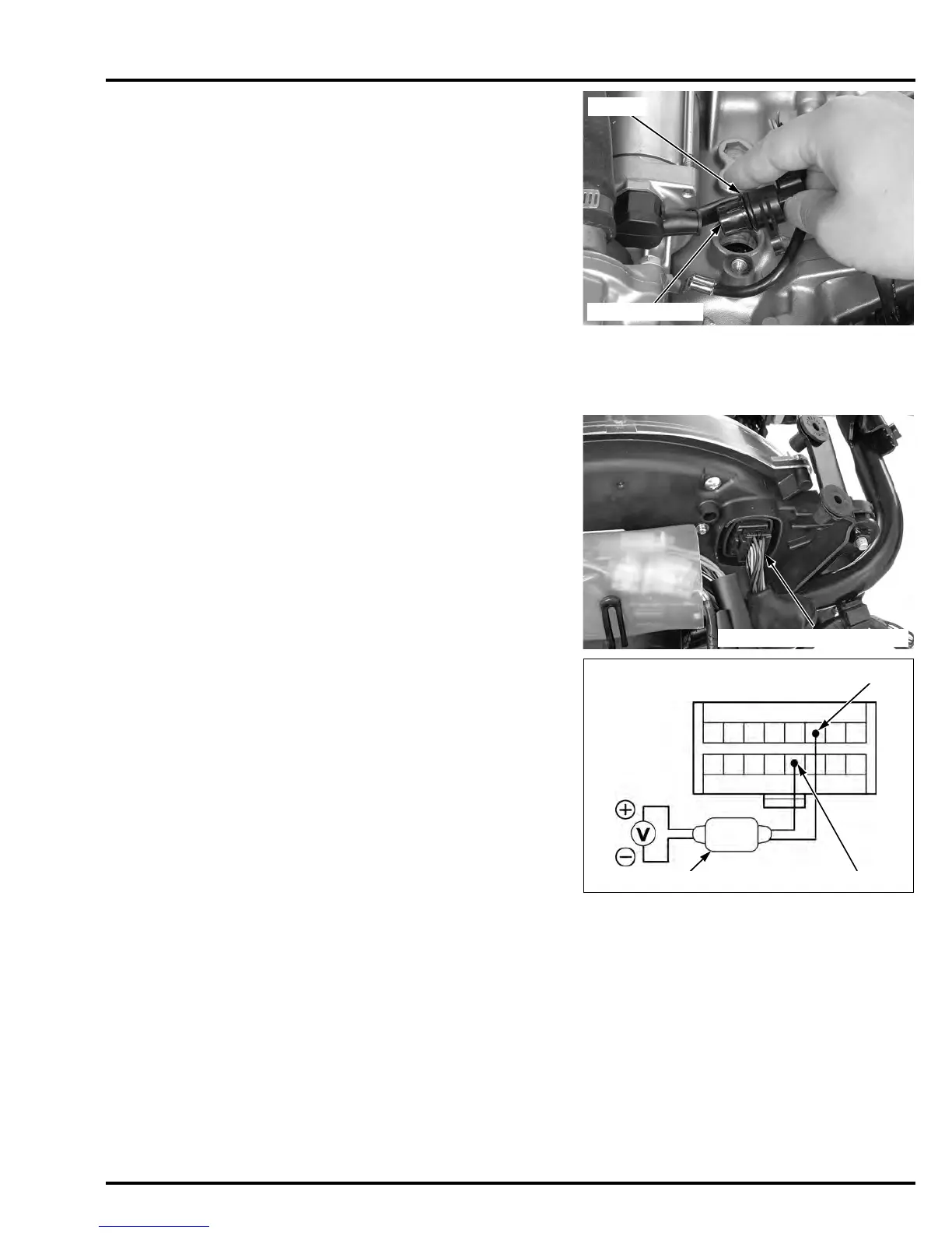
TACHOMETER
SYSTEM INSPECTION
CBF600S/SA:
Remove the front center cowl (page 2-10).
Disconnect the combination meter 16P (Black) con-
nectors.
Connect the peak voltage adaptor to the tachometer
Yellow/green (+) terminal and Green/black (–).
Start the engine and measure the tachometer input
peak voltage.
If the peak voltage is normal, replace the combina-
tion meter circuit board (page 20-13).
If the measured value is below 10.5 V, replace the
ECM (page 5-97).
TOOLS:
Imrie diagnostic tester (model 625) or
Peak voltage adaptor 07HGJ-0020100
with commercially available digital multimedia
(impedance 10 MΩ/DCV minimum)
CONNECTION: Yellow/Green (+) and Green/black (-)
PEAK VOLTAGE: 10.5 V minimum
PEAK VOLTAGE ADAPTER
Viewed from harness side/
the 16P connector:
Yellow/green
Green/black
Manuals by Motomatrix / www.motomatrix.co.uk / The Solution For Lost Motorcycle Coded Keys.
email: info@motomatrix.co.uk
 Loading...