ANTI–LOCK BRAKE SYSTEM (ABS; CBF600SA/NA)
16-4
SERVICE INFORMATION
GENERAL
• Be careful not to damage the wheel speed sensor and pulser ring when servicing.
• This section covers service of the Anti-lock Brake System (ABS). For other service of the conventional brake system
(page 15-4).
• When the ABS control unit detects a problem, it stops the ABS function and switches back to the conventional brake
operation, and the ABS indicator blinks or stays on. Take care during the test ride.
• Troubles not resulting from a faulty ABS (e.g. brake disc squeak, unevenly worn brake pad) cannot be recognized by the
ABS diagnosis system.
• Read "ABS self-diagnosis information" and "Before Troubleshooting" carefully, inspect and troubleshoot the ABS sys-
tem according to the Diagnostic Troubleshooting. Observe each step of the procedures one by one. Write down the
problem code and probable faulty part before starting diagnosis and troubleshooting.
• After troubleshooting, erase the problem code and perform the pre-start self-diagnosis to be sure that the ABS indicator
is operating normally.
• When the wheel speed sensor and/or pulser ring is replaced, check the clearance (air gap) between both components.
• The ABS control unit (ECU) is mounted on the modulator (the modulator with the built-in ECU). Do not disassemble the
ABS modulator. Replace the ABS modulator as an assembly when the it is faulty.
• The ABS modulator may be damaged if dropped. Also if a connector is disconnected when current is flowing, the exces-
sive voltage may damage the ECU. Always turn off the ignition switch before servicing.
• The following color codes are used throughout this section.
TORQUE VALUES
TOOL
Bu = Blue G = Green Lg = Light Green R = Red
Bl = Black Gr = Gray O = Orange W = White
Br = Brown Lb = Light Blue P = Pink Y = Yellow
Front wheel pulser ring mounting bolt 7 N·m (0.7 kgf·m, 5.2 lbf·ft) ALOC bolt; replace with a new one
Rear wheel pulser ring mounting bolt 7 N·m (0.7 kgf·m, 5.2 lbf·ft) ALOC bolt; replace with a new one
Brake pipe joint nut 14 N·m (1.4 kgf·m, 10 lbf·ft)
PCV mounting bolt 12 N·m (1.2 kgf·m, 9 lbf·ft)
Delay valve mounting bolt 12 N·m (1.2 kgf·m, 9 lbf·ft)
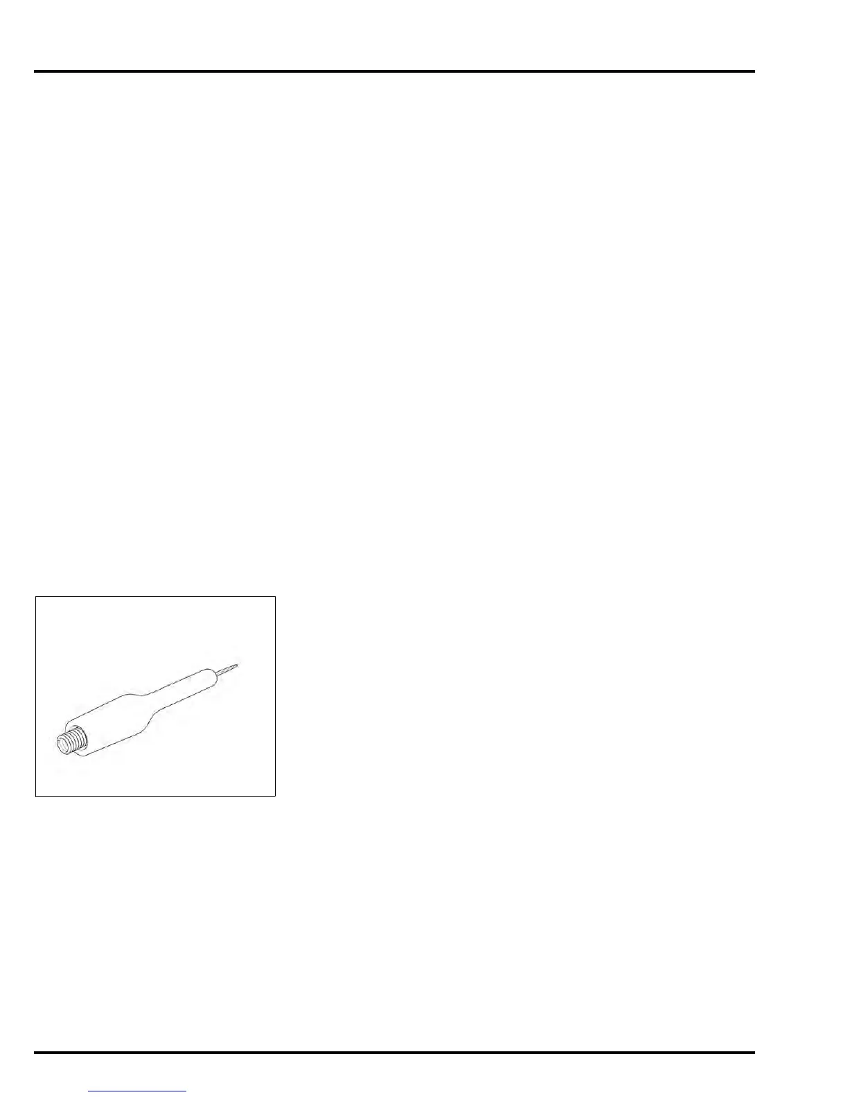
Test probe
07ZAJ-RDJA110
Manuals by Motomatrix / www.motomatrix.co.uk / The Solution For Lost Motorcycle Coded Keys.
email: info@motomatrix.co.uk