FUEL SYSTEM (PGM-FI)
5-36
MIL TROUBLESHOOTING
MIL 1 BLINK (MAP SENSOR)
• Before starting the inspection, check for loose or
poor contact on the MAP sensor 3P (Black) con-
nector and ECM 33P connectors, then recheck
the MIL blinking.
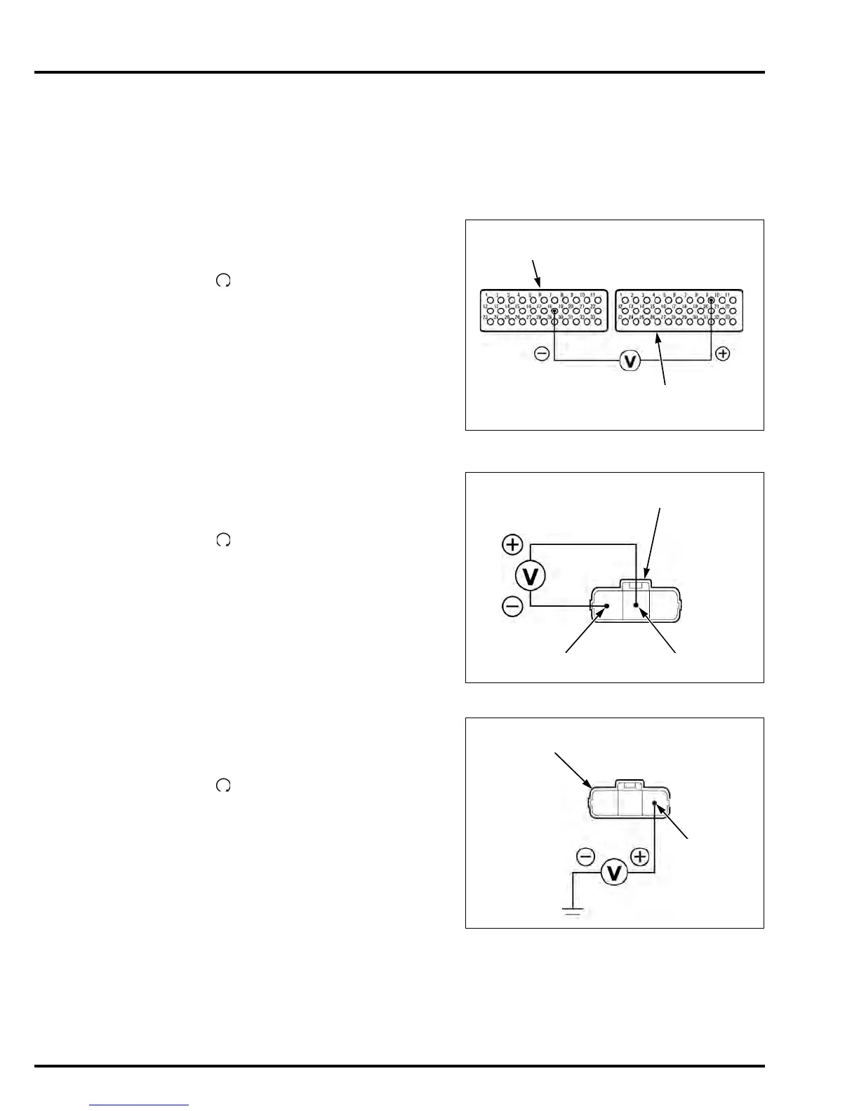
1. MAP Sensor Output Voltage Inspection
Turn the ignition switch OFF.
Connect the ECM test harness to ECM connec-
tors (page 5-14).
Turn the ignition switch ON and engine stop
switch " ".
Measure the voltage at the test harness termi-
nals.
Is the voltage within 2.7 – 3.1 V?
YES – Intermittent failure
NO – • About 5 V
GO TO STEP 2.
• About 0 V
GO TO STEP 3.
2. MAP Sensor Output Line Inspection
Turn the ignition switch OFF.
Disconnect the MAP sensor 3P (Black) connec-
tor.
Turn the ignition switch ON and engine stop
switch " ".
Measure the voltage at the wire harness side.
Is the voltage within 2.7 – 3.1 V?
YES – Faulty MAP sensor
NO – • Open circuit in Light green/yellow
wire
• Open circuit in Green/orange wire
3. MAP Sensor Input Voltage Inspection
Turn the ignition switch OFF.
Disconnect the MAP sensor 3P (Black) connec-
tor.
Turn the ignition switch ON and engine stop
switch " ".
Measure the voltage at the wire harness side.
Is the voltage within 4.75 – 5.25 V?
YES – GO TO STEP 4.
NO – GO TO STEP 5.
CONNECTION: B9 (+) – A18 (–)
TEST HARNESS PIN BOX
(A TERMINALS)
TEST HARNESS PIN BOX
(B TERMINALS)
(A18)
(B9)
CONNECTION: Light green/yellow (+) – Green/
orange (–)
3P (Black) CONNECTOR
(Wire side/female terminals)
Light green/yellowGreen/orange
CONNECTION: Yellow/red (+) – Ground (–)
3P (Black) CONNECTOR
(Wire side/female terminals)
Yellow/red
Manuals by Motomatrix / www.motomatrix.co.uk / The Solution For Lost Motorcycle Coded Keys.
email: info@motomatrix.co.uk


 To Next Page