LIGHTS/METERS/SWITCHES
20-26
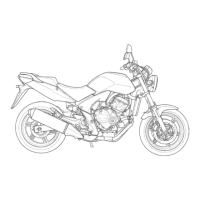
If the value is 0 V, check for continuity between the
combination meter 20P connector and ECM 33P
(Light gray) connector Yellow/green terminals.
If there is no continuity, check the wire harness for
an open circuit.
If there is continuity, replace the ECM (page 5-97).
CBF600N/NA:
Remove the headlight unit (page 20-7).
Disconnect the combination meter 9P (Natural) and
9P (Black) connectors.
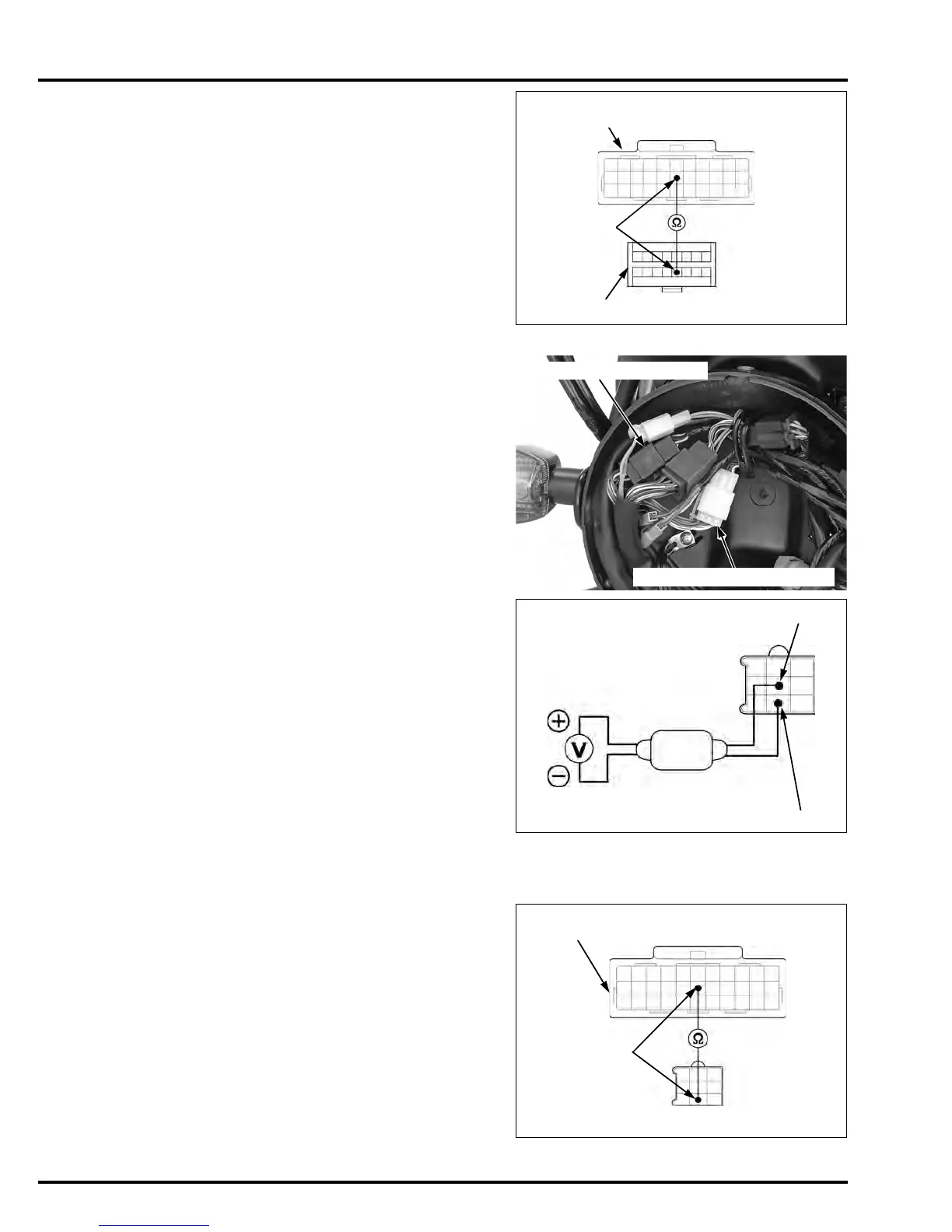
Connect the peak voltage adaptor to the tachometer
Yellow/Green (+) terminal and Green/black (–).
Start the engine and measure the tachometer input
peak voltage.
If the peak voltage is normal, replace the combina-
tion meter circuit board (page 20-13).
If the measured value is below 10.5 V, replace the
ECM (page 5-97).
If the value is 0 V, check for continuity between the
combination meter 9P connector and ECM 33P
(Light gray) connector Yellow/green terminals.
If there is no continuity, check the wire harness for
an open circuit.
If there is continuity, replace the ECM (page 5-97).
TOOL:
Test probe 07ZAJ-RDJA110
33P (Light gray) CONNECTOR
(Wire side/female terminals)
16P CONNECTOR (Viewed from harness side)
Yellow/green
9P (Black) CONNECTOR
9P (Natural) CONNECTOR
TOOLS:
Imrie diagnostic tester (model 625) or
Peak voltage adaptor 07HGJ-0020100
with commercially available digital multimedia
(impedance 10 MΩ/DCV minimum)
CONNECTION: Yellow/Green (+) and Green/black (-)
PEAK VOLTAGE: 10.5 V minimum
TOOL:
Test probe 07ZAJ-RDJA110
Yellow/green
Green/black
9P (Black) CONNECTOR
(Viewed from harness side)
33P (Light gray) CONNECTOR
(Wire side/female terminals)
9P CONNECTOR (Viewed from harness side)
Yellow/green
Manuals by Motomatrix / www.motomatrix.co.uk / The Solution For Lost Motorcycle Coded Keys.
email: info@motomatrix.co.uk
 Loading...