HYDRAULIC BRAKE
15-28
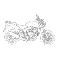
Install the push rod into the master cylinder.
Install the snap ring using the special tool as shown.
Apply silicone grease to the boot inside and install
the boot into the master cylinder.
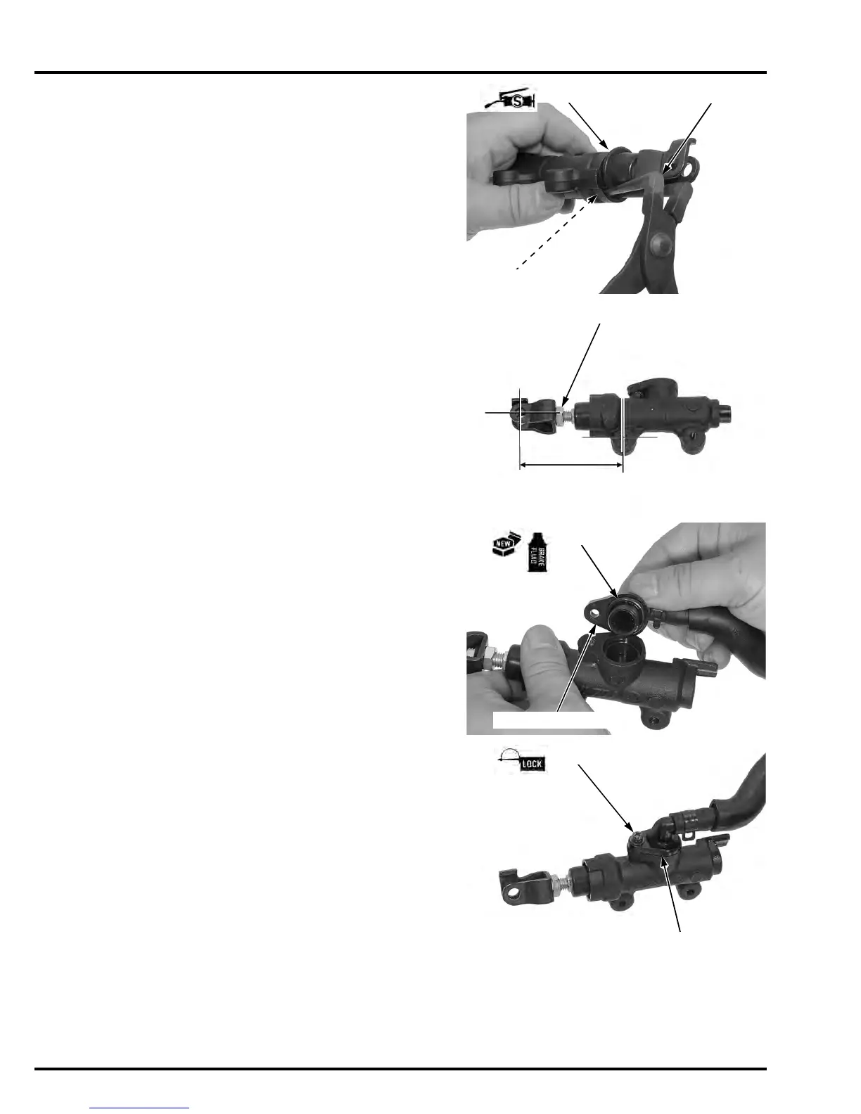
If the push rod is disassembled, adjust the push rod
length as shown.
After adjustment, tighten the lock nut to the speci-
fied torque.
Apply brake fluid to a new O-ring and install it onto
the reservoir joint.
Install the reservoir joint into the master cylinder.
Apply a locking agent to the reservoir joint screw
threads.
Install and tighten the screw to the specified torque.
Be certain the snap
ring is firmly seated
in the groove.
TOOL:
Snap ring pliers 07914-SA50001
SNAP RING PLIERS
BOOT
SNAP RING
TORQUE: 17 N·m(1.7kgf·m, 13 lbf·ft)
JOINT NUT
67.5 mm (2.66 in)
TORQUE: 1.5 N·m(0.2kgf·m, 1.1 lbf·ft)
Manuals by Motomatrix / www.motomatrix.co.uk / The Solution For Lost Motorcycle Coded Keys.
email: info@motomatrix.co.uk
 Loading...