ENGINEERING MANUAL OF AUTOMATION CONTROL
ELECTRIC CONTROL FUNDAMENTALS
111
LINE
VOLTAGE
TRANSFORMER
WRB WRB
WRB
T1
T2
DISCHARGE AIR
LOW LIMIT
CONTROLLER
ROOM
CONTROLLER
135
135
HOT WATER
VALVE
TO
COIL
ACTUATOR
C2526
LINE
VOLTAGE
TRANSFORMER
WRB WR B
WRB
T1
T2
ROOM
CONTROLLER
135
135
DISCHARGE AIR
HIGH LIMIT
CONTROLLER
TO
COIL
VALVE
HOT WATER
ACTUATOR
C2527
When the high-limit controller calls for less heat, the poten-
tiometer wiper R (shown dotted) moves halfway from B to W.
This causes an unbalance of 70 ohms (210 – 140) in the right
leg of the bridge as shown in the following table:
Left Leg Right Leg
Controller potentiometer 140 0
High-limit potentiometer 0 70
Feedback potentiometer
0 140
Total 140 210
The unbalance causes the electronic relay to trigger the left
triac, energize the ccw motor winding, and drive the actuator
drive shaft toward closed. Since half of the 70-ohm unbalance
has to go on each side of the bridge to rebalance the circuit, the
feedback potentiometer moves 35 ohms to the right. The table
then appears as follows:
Left Leg Right Leg
Controller potentiometer 140 0
High-limit potentiometer 0 70
Feedback potentiometer
35 105
Total 175 175
When the feedback potentiometer reaches the new position
(shown dotted) the bridge is rebalanced, the left triac turns
off, and the actuator drive shaft stops in the new position
(75 percent open).
CONTROL COMBINATIONS
The following illustrates common applications of Series 90
controls including low- and high-limit controls from an
application viewpoint.
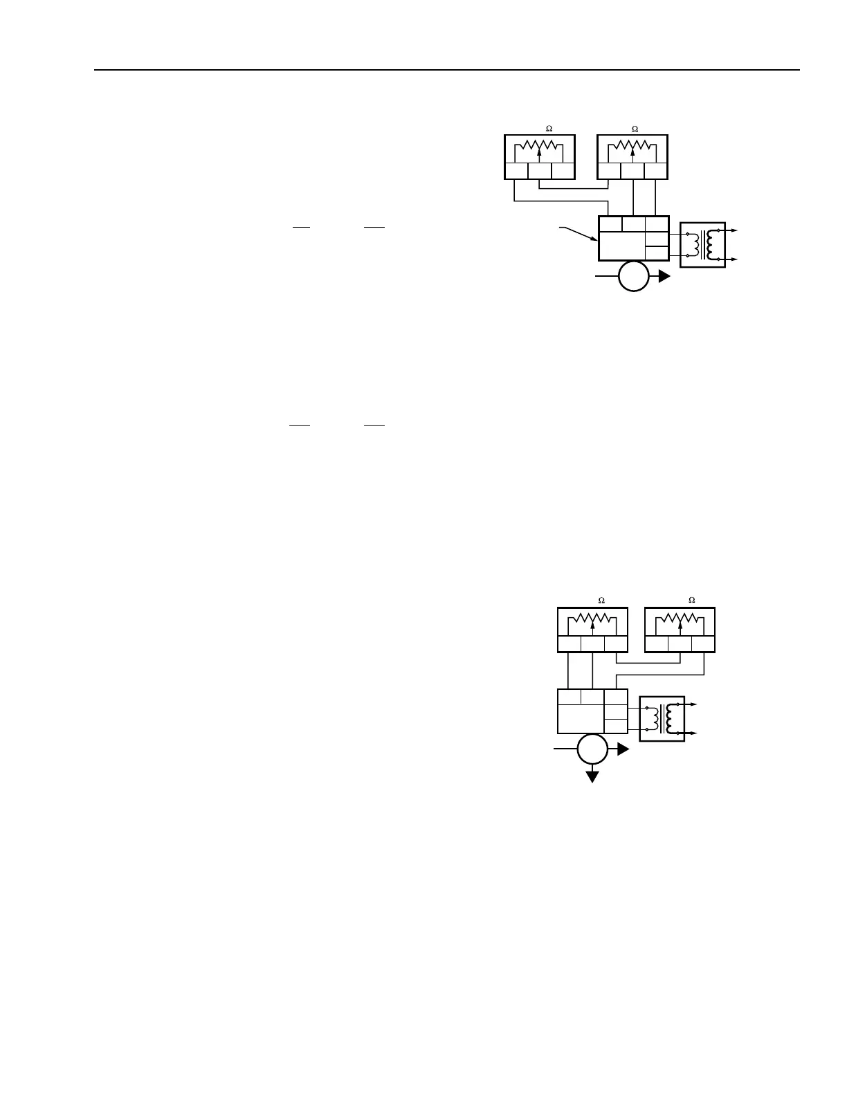
LOW-LIMIT CONTROL
Figure 25 illustrates a typical Series 90 circuit for a heating
application with a room controller, motorized valve, and a low-
limit controller located in the discharge air to the space. The
temperature of the space can rise rapidly as a result of increased
solar radiation, occupancy, or other conditions resulting in a
sudden decrease in heating load. The room controller is then
satisfied and closes the valve to the heating coil. If the system
uses outdoor air, closing the valve to the heating coil can cause
air to be discharged into the room at a temperature lower than
desirable. To correct this, the low-limit controller causes the
valve to move toward open thus limiting the low temperature
of the discharge air.
Fig. 25. Series 90 Circuit with Low-Limit Control.
HIGH-LIMIT CONTROL
Figure 26 illustrates a typical Series 90 circuit for a heating
application with a room controller, motorized valve, and high-
limit controller located in the discharge air to the space. This
circuit is used when there is danger of the temperature rising
too high. The high-limit controller takes over control of the
valve to the heating coil if the discharge air temperature rises
above a comfortable level. This circuit is similar to the low-
limit circuit except that the high-limit controller is in the B
leg of the actuator circuit and drives the actuator toward the
closed position.
Fig. 26. Series 90 Circuit with High-Limit Control.