ENGINEERING MANUAL OF AUTOMATIC CONTROL
DAMPER SELECTION AND SIZING
456
In a low leakage damper, materials for the seals are selected
based on the temperature of the air being controlled. Standard
seals can be upgraded to withstand higher temperatures by using
a more heat resistant material. An example would be changing
a blade edge seal from neoprene to silicone rubber.
When duct static pressure is relatively low but leakage must
be minimal, a low leakage damper with reduced static pressure
ratings may be used. Generally, as the strength of a given damper
increases, velocity and static pressure drop capabilities increase.
SMOKE DAMPERS
Any damper that controls airflow is capable of controlling
smoke. In order to apply dampers to smoke control systems
properly, UL 555S, Standard for Leakage Rated Dampers for
Use in Smoke Control Systems, provides classification based
on leakage, differential pressure across the damper, maximum
velocity when the damper is fully open, temperature, and
damper size. This classification includes the specific actuator
used. See Table 1 for leakage classifications.
Table 1. UL 555S Maximum Allowable
Damper Leakage Classifications.
In designing a smoke damper, a manufacturer develops a
product line with Maximum A and B and Minimum A and B
dimensions where:
A= Overall damper size in the direction of the
blade length.
B= Overall damper size perpendicular to the blade
length.
The three damper sizes tested by UL are Maximum A/Minimum
B, Minimum A/Maximum B, and Maximum A/Maximum B.
Damper testing includes meeting material construction
requirements, cycling, temperature degradation, dust loading,
salt-spray exposure, leakage, and operation at maximum
pressure and velocity.
In testing for temperature degradation, the damper is heated
in the closed position for 30 minutes and then cycled to see
that it operates as intended. Temperature classifications include
250F, 350F, 450F, etc., in 100F increments.
Generally, Classes I, II, III, and IV are considered appropriate
for smoke control. The class specified should be based on the
application requirements. For example, Classes I and II are
appropriate for mixed air dampers on systems having return
fans. Classes II and III are appropriate for zone dampers where
more leakage is acceptable. Classes III and IV are applicable
to dampers that always modulate, such as in stairwell
pressurization systems.
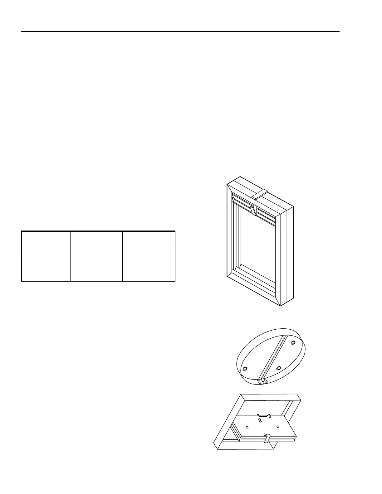
FIRE DAMPERS
Fire dampers are used in HVAC systems to prevent
superheated air, gases, or flames from crossing a fire barrier
through an air duct. Fire dampers are usually not used in
modulating airflow control applications and are designed for
extreme operating environments. Fire dampers are rated in hours
of exposure in a specified test environment. Construction and
performance of fire dampers (Fig. 11 and 12) is governed by
UL Standard 555.
Fig. 11. Wall/Partition Fire Damper.
M10416
Fig. 12. Ceiling Fire Dampers.
Leakage
Classification
Cfm per sq ft
at 1 in. wc
Cfm per sq ft
at 4 in. wc
O
I
II
III
IV
0
4
10
40
60
0
8
20
80
120