ENGINEERING MANUAL OF AUTOMATION CONTROL
BUILDING AIRFLOW SYSTEM CONTROL APPLICATIONS
273
noise. They work up to a maximum static
pressure of 3 in. wc.
—Vaneaxial fans are basically tubeaxial fans with
straightening vanes added to avoid spiraling air
patterns. They are space efficient, quieter than
tubeaxial fans, and work at static pressures up to
10 in. wc.
FAN PERFORMANCE TERMS
The following are terms used when discussing fan
performance:
Fan volume: The airflow passing through the fan outlet.
Generally this fan outlet value is only slightly less than
the airflow at the fan inlet because specific volume
changes due to air compression are small.
Fan outlet velocity: The fan volume divided by the fan outlet
area. This velocity is a theoretical value because, in
reality, the velocity pattern at the outlet of a fan is not
easy to measure.
Fan Static Pressure (FSP): The fan total pressure minus the
fan velocity pressure (FSP = FTP – FVP). It can be
calculated by subtracting the total pressure at the fan
inlet from the static pressure at the fan outlet.
Fan Total Pressure (FTP): The difference between the total
pressure at the fan inlet and the total pressure at the
fan outlet. The FTP value measures the total
mechanical energy added to the air by the fan.
Fan Velocity Pressure (FVP): The velocity pressure
corresponding to the fan outlet velocity.
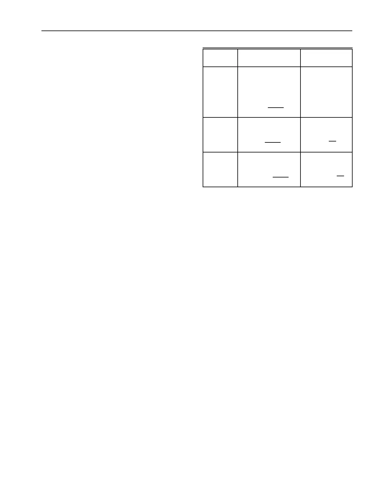
FAN LAWS
Fan laws (Table 1) are simple and useful when dealing with
changing conditions. Three important laws deal with speed
changes:
1. Airflow varies directly with the fan speed. For example,
doubling the fan speed (rpm) doubles the airflow (cfm)
delivery.
2. Static pressure varies as the square of the fan speed. For
example, doubling the fan speed (rpm) develops four
times the static pressure (in. wc).
3. Power varies as the cube of the fan speed. For example,
doubling the fan speed (rpm) requires eight times the fan
power (hp).
Table 1. Fan Laws
When When
Variable
Speed Changes Density Changes
Varies DIRECT with
Speed Ratio
Does Not Change
Airflow
CFM
2
=
CFM
1
()
RPM
2
RPM
1
2
Varies with SQUARE
of Speed Ratio
Varies DIRECT
with Density Ratio
Pressure
P
2
= P
1
()
RPM
2
RPM
1
2
P
2
= P
1
()
D
2
D
1
Varies with CUBE of
Speed Ratio
Varies DIRECT
with Density Ratio
Horsepower
HP
2
= HP
1
()
RPM
2
RPM
1
3
HP
2
= HP
1
()
D
2
D
1
FAN HORSEPOWER
The theoretical horsepower (hp) required to drive a fan is
the horsepower required if there were no losses in the fan (100
percent efficiency). The horsepower formula is:
Theoretical hp = (cfm x FTP) ÷ 6356
Where:
cfm = Quantity of air
6356 = A constant for English units
FTP = Fan total pressure.
Brake horsepower (bhp) is the actual horsepower required to
drive the fan.
bhp = Theoretical hp ÷ Fan efficiency
=(cfm x FTP) ÷ (6356 x Fan efficiency)
The brake horsepower is always larger than the theoretical
horsepower due to inefficiencies. The actual brake horsepower
of the fan can be determined only by testing.