ENGINEERING MANULA OF AUTOMATIC CONTROL
INDIVIDUAL ROOM CONTROL APPLICATIONS
405
An economical alternative to reheating air that has been
cooled or reducing the reheat requirement is to reset the setpoint
of primary air in the central fan system conditioning section.
Primary air reset limits are usually required to assure adequate
dehumidification.
The VAV ATU configurations in Figures 5 through 9 are
pressure-independent.
Variable Air Volume ATU
The variable air volume ATU (Fig. 5) is a pressure-
independent unit which delivers the required air volume to the
space regardless of the supply static pressure. The amount of
air delivered is derived from a space temperature PI loop. A
flow sensor in the supply airflow modulates the damper actuator
to control air volume. The room sensor resets the airflow
setpoint as the space thermal load changes. The airflow control
loop can be set to maintain minimum airflow at light load
conditions, while, maximum airflow can be set to limit flow to
meet design conditions. A single wall module can be directed
to multiple controllers to control multiple ATUs with the same
or differing volume ratings.
M10538
75
74
00
24 75 77
MINIMUM
DAMPER
POSITION
MAXIMUM
DAMPER
POSITION
-2.5
HEATING
DEADBAND
CURRENT
TEMPERATURE
SPACE
TEMPERATURE
SETPOINT SCHEDULE
OPEN
ACTUATOR
POSITION
CLOSED
MINIMUM
POSITION
REHEAT
POSITION
MAXIMUM
POSITION
LOWHIGH
VALVE
DAMPER
RHC
LOW
HIGH
SPACE
HEATING LOAD
HEATING SETPOINT
COOLING SETPOINT
SPACE
COOLING LOAD
DEADBAND
PERCENT
OPEN
PERCENT
OPEN
PRIMARY
AIR
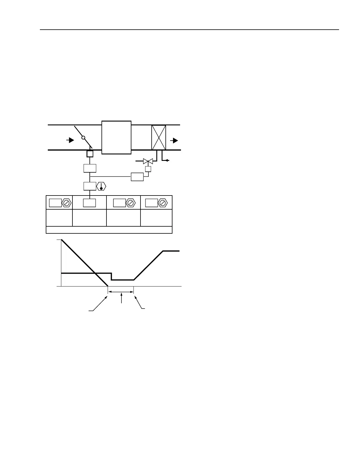
Figure 4 shows a reheat coil added to a throttling VAV ATU.
In this application, the temperature controller sequences the
operation of the damper actuator and the control valve or reheat
coil. The coil can be replaced by single or multiple stages of
electric resistance heat. The damper modulates under PI control
at the cooling setpoint and the hot water valve modulates under
a separate PI control at the heating setpoint, with a deadband
between heating and cooling. In this example, the space
occupant can adjust the wall module temperature cooling
setpoint (displayed as SPACE TEMPERATURE in the setpoint
schedule) and the BMS operator can adjust for the deadband
between cooling and heating.
Fig. 4. Throttling VAV Air Terminal
Unit with Reheat Coil.