ENGINEERING MANUAL OF AUTOMATIC CONTROL
CHILLER, BOILER, AND DISTRIBUTION SYSTEM CONTROL APPLICATIONS
316
Fig. 21. Schematic of Combination Absorption/
Centrifugal Chiller System Steam Piping
and Control Circuit.
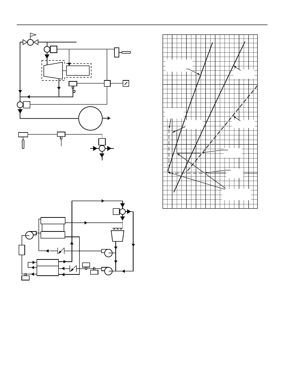
Fig. 23. Typical Steam Consumption, Individual
and Combination Chillers.
CHILLER PUMP OPTIMIZATION
Pump configuration (variable water flow versus constant
water flow) also affects chiller system efficiency. Constant water
flow causes the largest change in efficiency from system no
load to design because the pump energy becomes a greater
percentage of the total energy input at light load conditions.
Va riable water flow, using two-way load valves or variable speed
pumps, maintains the pump load at nearly a constant percentage
of the total energy input at all loads. If a chiller system has
constant water flow, chiller optimization must include pump
energy usage as part of the power calculation to account for
energy cost variations over the range of loads. In a chiller system
using variable water flow, it is not necessary to account for
pump energy cost. Refer to HOT AND CHILLED WATER
DISTRIBUTION SYSTEMS AND CONTROL.
Fig. 22. Schematic of Combination Absorption/
Centrifugal Chiller System Water Piping.
Figure 23 compares the steam consumption of individual
chillers to a combination system showing the savings using the
combination system. The range of centrifugal cutout points
indicates where most centrifugal chillers are shut down and the
absorption chiller provides all cooling required by the system.
CONDENSER
COMPRESSOR
EVAPORATOR
CONDENSER
CHILLER 1
LOAD
C2689
ABSORBER
EVAPORATOR
ABSORPTION
CHILLER
CENTRIFUGAL
CHILLER
COOLING
TOWER
COOLING TOWER
BYPASS VALVE
P2
T2
V2
T1
REFRIGERATION (TONS)
0
100
200
300
400
500
600
700
800
900
1000
0
1
2
3
4
5
6
7
8
9
10
11
12
13
14
15
16
17
18
19
C1047
TURBINE-DRIVEN
CENTRIFUGAL
CHILLER
15%
CENTRIFUGAL
CAPACITY
25%
CENTRIFUGAL
CAPACITY
RANGE OF
CENTRIFUGAL
CUTOUT
18%
SYSTEM
LOAD
33%
SYSTEM
LOAD
COMBINATION
SYSTEM
ABSORPTION
CHILLER
STEAM CONSUMPTION (1000 LB/HR)
BACK
PRESSURE
TURBINE
COMPRESSOR
TO INLET VANE
ACTUATOR
T1
T2
SENSOR IN
CHILLED
WATER
SUPPLY
RELAY
PRESSURE
CONTROLLER
P1
PRESSURE
CONTROLLER
P2
ABSORPTION/
COMBINATION
SELECTOR
SWITCH
HIGH PRESSURE
STEAM SUPPLY
PRV SET
APPROX.
10 PSI
CENTRIFUGAL
CHILLER
ABSORPTION CHILLER
CAPACITY CONTROL VALVE
ABSORPTION
CHILLER
GENERATOR
CONDENSATE
RETURN
SENSING
ELEMENT IN
CONDENSER
WATER SUPPLY
TO ABSORBER
DISCHARGE OF
ABSORPTION
CHILLER
CONDENSER
WATER PUMP
CWR
TO
COOLING
TOWER
COOLING TOWER
BYPASS
C2690