PNEUMATIC CONTROL FUNDAMENTALS
ENGINEERING MANUAL OF AUTOMATIC CONTROL
66
alternately, so wear is spread over both machines, each capable
of supplying the average requirements of the system without
operating more than half the time. In the event of failure of
one compressor, the other assumes the full load.
Contamination in the atmosphere requires a compressor
intake filter to remove particles that would damage the
compressor pump. The filter is essential on oil-less compressors
because a contaminated inlet air can cause excessive wear on
piston rings. The intake filter is usually located in the equipment
room with the compressor, but it may be located outdoors if
clean outdoor air is available. After the air is compressed,
cooling and settling actions in the tank condense some of the
excess moisture and allow fallout of the larger oil droplets
generated by the compressor pump.
A high pressure safety relief valve which opens on
excessively high tank pressures is also required. A hand valve
or automatic trap periodically blows off any accumulated
moisture, oil residue, or other impurities that collect in the
bottom of the tank.
AIR DRYING TECHNIQUES
GENERAL
Air should be dry enough to prevent condensation. Con-
densation causes corrosion that can block orifices and valve
mechanisms. In addition, dry air improves the ability of filters
to remove oil and dirt.
Moisture in compressed air is removed by increasing
pressure, decreasing temperature, or both. When air is
compressed and cooled below its saturation point, moisture
condenses. Draining the condensate from the storage tank
causes some drying of the air supply, but an air dryer is often
required.
An air dryer is selected according to the amount of moisture
in the air and the lowest temperature to which an air line will
be exposed. For a chart showing temperature and moisture
content relationships at various air pressures, refer to the
General Engineering Data section.
DRY AIR REQUIREMENT
The coldest ambient temperature to which tubing is exposed
is the criterion for required dryness, or dew point. Dew point
is the temperature at which moisture starts to condense out
of the air.
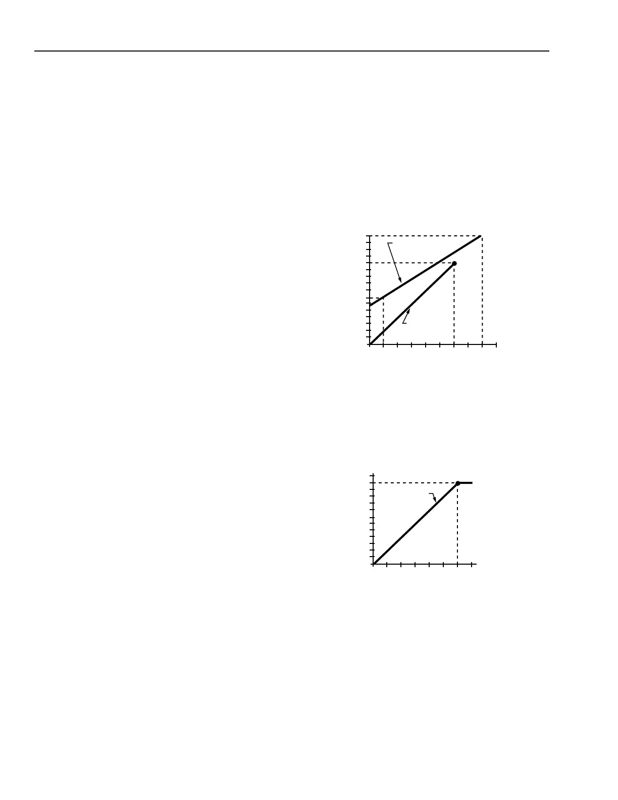
The coldest winter exposure is normally a function of
outdoor air temperature. Summer exposure is normally a
function of temperature in cold air ducts or air conditioned
space. The typical coldest winter application is an air line and
control device (e.g., damper actuator) mounted on a rooftop
air handling unit and exposed to outdoor air temperatures (Fig.
12). The second coldest winter exposure is an air line run in a
furred ceiling or outside wall.
70
60
50
40
30
20
10
0
-10
-10 0 10 20 30 4050607080
C1098
OUTDOOR AIR TEMPERATURE (°F)
REQUIRED MAXIMUM
DEWPOINT OF MAIN AIR (°F)
24
TUBING IN
FURRED
CEILING
TUBING AT
OUTDOOR AIR
TEMPERATURE
Fig. 12. Winter Dew Point Requirement.
A typical summer minimum dew point application is a cold
air plenum. Figure 13 shows a 50F plenum application along
with winter requirements for a year-round composite.
50
40
30
20
10
0
-10
-10 0 10 20 30405060
C1099
OUTDOOR AIR TEMPERATURE (°F)
REQUIRED MAXIMUM
DEWPOINT OF MAIN AIR (°F)
SUMMER REQUIREMENT
COLD AIR PLENUM
WINTER
REQUIREMENT
AT OUTDOOR AIR
TEMPERATURE
Fig. 13. Twelve-Month Composite Dew Point
Requirement.