PNEUMATIC CONTROL FUNDAMENTALS
67
ENGINEERING MANUAL OF AUTOMATIC CONTROL
CONDENSING DRYING
The two methods of condensing drying are high-pressure
drying and refrigerant drying.
High-Pressure Drying
High-pressure drying may be used when main air piping is
kept away from outside walls and chilling equipment. During
compression and cooling to ambient temperatures, air gives
up moisture which then collects in the bottom of the storage
tank. The higher the tank pressure, the greater the amount of
moisture that condenses. Maintaining a high pressure removes
the maximum amount of moisture. The compressor should have
a higher operating pressure than is required for air supply
purposes only. However, higher air pressure requires more
energy to run the compressor. The tank must include a manual
drain valve or an automatic trap to continually drain off
accumulated moisture. With tank pressures of 70 to 90 psi, a
dew point of approximately 70F at 20 psi can be obtained.
Refrigerant Drying
Lowering air temperature reduces the ability of air to hold
water. The refrigerated dryer (Fig. 14) is the most common
means of obtaining dry, compressed air and is available in
several capacities. It provides the greatest system reliability
and requires minimal maintenance.
The heat exchanger reduces the temperature of the com-
pressed air passing through it. A separator/filter condenses
both water and oil from the air and ejects the condensate
through a drain. A temperature-sensing element controls the
operation of the refrigeration system to maintain the tempera-
ture in the exchanger.
With a dew point of 35F and an average compressor tank
pressure of 80 psi, air is dried to a dew point of 12F at 20 psi.
Under severe winter conditions and where piping and devices
are exposed to outside temperatures, the 12F dew point may
not be low enough.
DESICCANT DRYING
A desiccant is a chemical that removes moisture from air. A
desiccant dryer is installed between the compressor and the
PRV. Dew points below –100F are possible with a desiccant
dryer. The desiccant requires about one-third of the process
air to regenerate itself, or it may be heated. To regenerate,
desiccant dryers may require a larger compressor to produce
the needed airflow to supply the control system and the dryer.
It may be necessary to install a desiccant dryer after the
refrigerant dryer in applications where the 12F dew point at
20 psi mainline pressure does not prevent condensation in air
lines (e.g., a roof-top unit exposed to severe winters).
The desiccant dryer most applicable to control systems uses
the adsorbent principle of operation in which porous materials
attract water vapor. The water vapor is condensed and held as
a liquid in the pores of the material. The drying action continues
until the desiccant is saturated. The desiccant is regenerated
by removing the moisture from the pores of the desiccant
material. The most common adsorbent desiccant material is
silica gel, which adsorbs over 40 percent of its own weight in
water and is totally inert. Another type of adsorbent desiccant
is the molecular sieve.
A desiccant is regenerated either by heating the desiccant
material and removing the resulting water vapor from the
desiccant chamber or by flushing the desiccant chamber with
air at a lower vapor pressure for heatless regeneration. To
provide a continuous supply of dry air, a desiccant dryer has
two desiccant chambers (Fig. 15). While one chamber is being
regenerated, the other supplies dry air to the system. The
cycling is accomplished by two solenoid valves and an electric
timer. During one cycle, air passes from the compressor into
the left desiccant chamber (A). The air is dried, passes through
the check valve (B), and flows out to the PRV in the control
system.
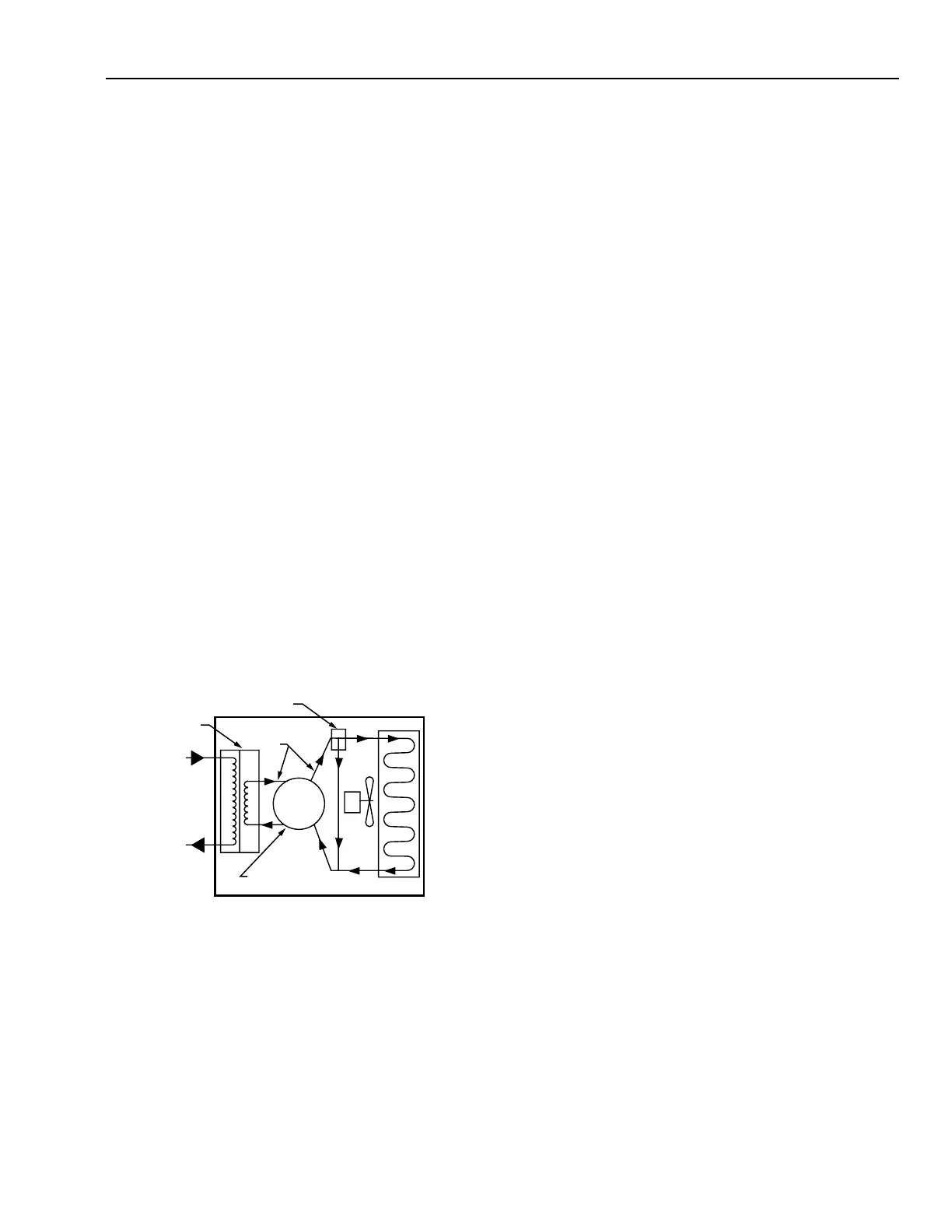
HOT GAS
BYPASS
CONTROL
HEAT
EXCHANGER
AIR IN
AIR OUT
REFRIGERANT
LINES
REFRIGERATION
UNIT
CONDENSOR
REFRIGERANT DRYER
C1888
Fig. 14. Typical Refrigerant Dryer Airflow Diagram.
The refrigerant dryer uses a non cycling operation with a
hot gas bypass control on the refrigerant flow to provide a
constant dew point of approximately 35F at the tank pressure.
The refrigeration circuit is hermetically sealed to prevent loss
of refrigerant and lubricant and to protect against dirt.