ENGINEERING MANUAL OF AUTOMATIC CONTROL
DAMPER SELECTION AND SIZING
463
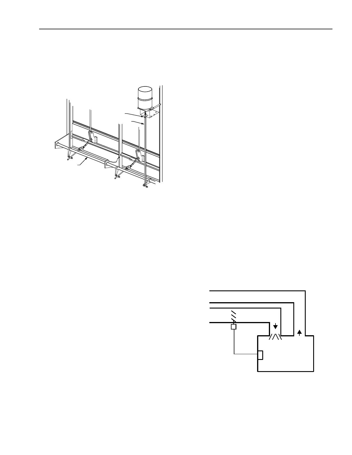
JACKSHAFTS
A jackshaft allows a single actuator to drive adjacent vertical
sections of a multiple section damper assembly with evenly
distributed force (Fig. 23). It provides adjustability and uniform
synchronized section-to-section operation.
Fig. 23. Damper Jackshaft Application.
ACTUATOR SELECTION
One method of selecting actuators for damper applications
is based on the number of square feet of damper to be positioned
related to a specific actuator. This data is usually provided in
tabular form in the manufacturer specifications and is valid for
specified static pressure and velocity levels only.
Another method of selecting actuators relates the total blade
width dimension of single and multisection dampers to the actuator
capability. The ratings of actuators are based on this dimension
and are given in tabular form in the manufacturer specifications.
LINKAGE
ASSEMBLY
PUSHROD
C2390
JACKSHAFT
DAMPER
ACTUATOR
THERMOSTAT
SPACE
C1494
DAMPER SIZING
Dampers are typically chosen based on duct size and
convenience of location. However, selection by these criteria
frequently results in oversized dampers which produce
undesirable system control results. Proper selection and sizing
of dampers provides the following benefits:
—Lower installation cost because damper sizes are smaller.
In addition, smaller actuators or a fewer number of them
are required.
— Reduced energy costs because smaller damper size allows
less overall leakage.
—Improved control characteristics (rangeability) because
the ratio of total damper flow to minimum controllable
flow is increased.
—Improved operating characteristics (linearity).
When selecting a damper, it is necessary to consider the
operating characteristics and capacities so the desired system
control is achieved. These items are discussed, along with
damper sizing, in this section.
SYSTEM CHARACTERISTICS
The damper system consists of the damper plus the series
resistance that relates to that particular damper (e.g., duct work,
mixing boxes, diffusers, and coils).
Figure 24 shows a typical control loop for a damper system.
The thermostat in the space contains the sensing element and
controller. The difference between the control point and setpoint
determines the correction signal from the controller. The
controller directs the actuator to open or close the damper. The
position of the damper determines the volume of the air flowing
and ultimately the temperature of the space.
Fig. 24. Control Loop for a Damper System.