ENGINEERING MANUAL OF AUTOMATIC CONTROL
CHILLER, BOILER, AND DISTRIBUTION SYSTEM CONTROL APPLICATIONS
318
COOLING TOWER AND CONDENSER
WATER CONTROL
COOLING TOWER PERFORMANCE
CHARACTERISTICS
The cooling tower dissipates the heat collected from the
building by the chiller and chilled water system by cooling the
condenser water. Evaporatively cooled condenser water will
cool refrigerant to within 7F of the outdoor air wet-bulb
temperature. Air cooled condensers will cool refrigerant to
within 20F of the outdoor air dry-bulb temperature. A cooling
tower normally provides a refrigerant head about 30F lower
than an air cooled condenser. This means an evaporative cooling
tower provides a significantly lower cooling cost than an air
cooled condenser.
Figure 25 shows water-air counterflow in a cooling tower. The
fill increases the time that the water and air are in contact making
the cooling tower more efficient. Fill is generally one of two types,
either splash or film type. A splash type fill is a series of slats over
which the water cascades. Film type fill causes the water to flow
down thin closely spaced vertical sheets of plastic.
Reprinted by permission from the ASHRAE
Handbook–1996 Systems and Equipment
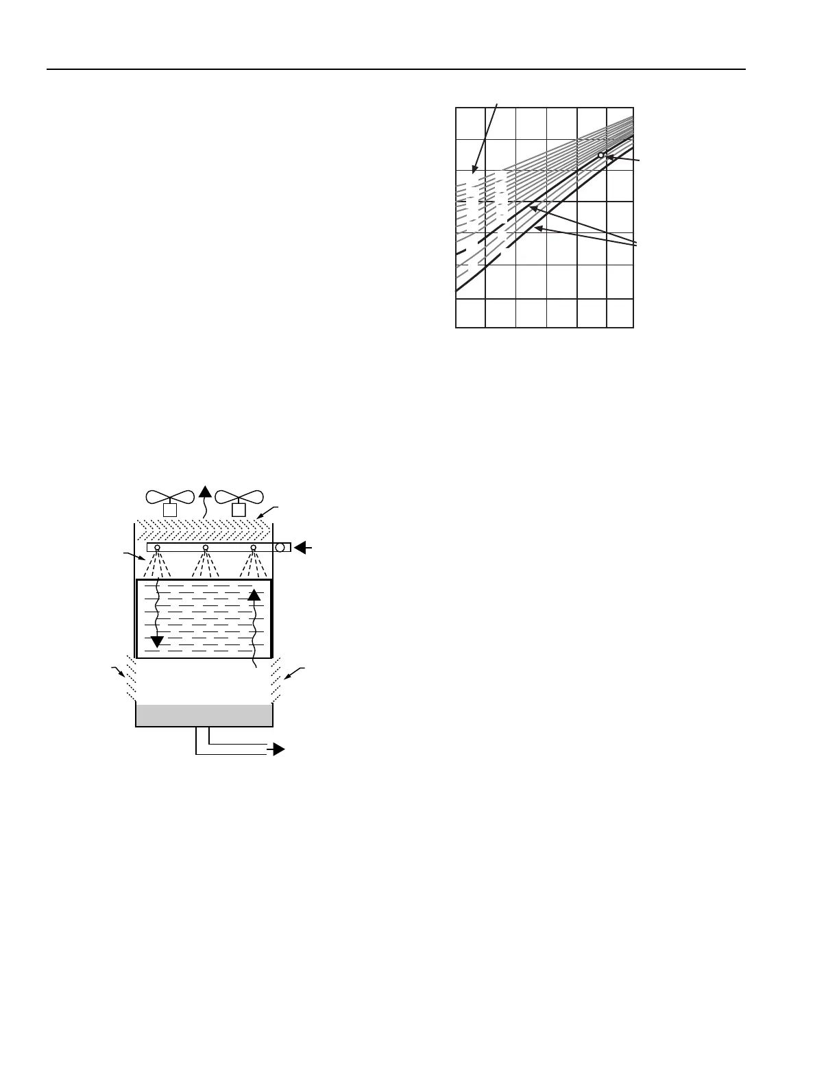
Fig. 26. Typical Cooling Tower
Partial Load Characteristics.
In Figure 26 summer design conditions are approximately
85F cold water leaving the tower, 95F water entering, and OA
wet-bulb of 78F. This is 7F approach at 10F range. Notice that
the point is plotted on the 10F range line. The same tower used
for free cooling at an OA wet-bulb of 50F would provide 65F
leaving water (15F approach) at full load (10F range) or 58F
water (8F approach) at 40 percent load (4F range).
COOLING TOWER CAPACITY CONTROL
Fan control is the usual method of reducing tower capacity
to maintain condenser water supply temperature in mild
weather. A tower bypass valve is used to further limit cooling
when the fans are off (Fig. 27). On-off fan control is very
difficult at light loads because at light load the OA WB is usually
well below design, which increases the tower capacity,
producing short fan “on” periods. Controlling the air volume
with dampers, blade pitch, or fan speed provides much closer
and more stable control. A variable speed fan is more efficient
than a two-speed fan when varying tower capacity.
Modulating tower water bypass for capacity control at low
ambient temperatures can cause freeze-up in some tower designs.
Since, use of a tower bypass mixing valve in the tower leaving
water can lower the pump suction pressure below the pumps
minimum NPSH, a diverting valve in the tower entering water
is generally used.
Fig. 25. Cooling Tower, Showing Water-Air Counterflow.
The range (inlet water temperature minus outlet water
temperature) at design load of a cooling tower is determined
by the amount of heat to be rejected and the water flow used to
carry this heat to the tower. The cooling capability is then
expressed as the design approach (approach specifies how close
to the OA WB a cooling tower can cool water) at design range.
Since most operation is at less than design load and/or design
outdoor air temperatures, partial load operating characteristics
have a strong influence on operating costs. Partial load operating
characteristics are also used to establish the cooling capacity
and capability for free cooling cycles at low outdoor air
temperatures. Partial load characteristics for a tower at design
flow rate are shown in Figure 26.
HEATED
AIR OUT
DRIFT
ELIMINATORS
HOT WATER
FROM
CONDENSER
AIR IN
AIR IN
TO CONDENSER
WATER PUMP
C2694
SPRAY
DISTRIBUTION
FILL
WATER
AIR
FREE COOLING
EXAMPLES
SUMMER DESIGN
CONDITIONS:
ENTERING WATER, 95F
LEAVING WATER, 85F
OA WET BULB, 78F
TEMPERATURE RANGE, °F
WATER TEMPERATURE, °F
100
90
80
70
60
50
40
30
30
40
50
60
70
80
30
26
22
18
14
10
6
28
24
20
16
12
8
4
C1479
OUTSIDE AIR WET BULB TEMPERATURE, °F