PNEUMATIC CONTROL FUNDAMENTALS
ENGINEERING MANUAL OF AUTOMATIC CONTROL
84
Fig. 55. Typical OPEN/AUTO/CLOSED Application.
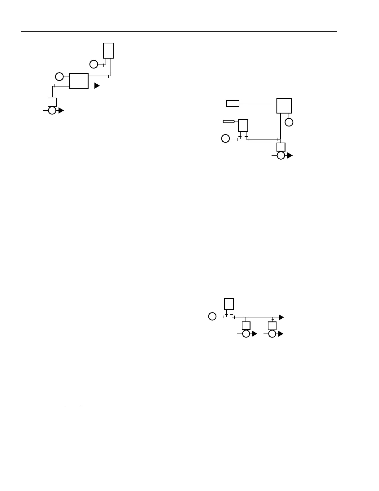
MANUAL POSITIONING SWITCH
A manual positioning switch is used to position a remote
valve or damper or change the setpoint of a controller. The
switch takes input air from a controller and passes a preset,
constant, minimum air pressure to the branch regardless of
the controller output (e.g., to provide an adjustable minimum
position of an outdoor air damper). Branchline pressure from
the controller to other devices connected to the controller is
not affected.
Figure 56 shows the switch functioning as a minimum
positioning switch. The damper will not close beyond the
minimum setting of the positioning switch. As the controller
signal increases above the switch setting, the switch positions
the damper according to the controller signal.
M
MB
DA
THERMOSTAT
TO OTHER
VALVES
N.O. HEATING COIL VALVES
C2349
PNEUMATIC CONTROL COMBINATIONS
Fig. 56. Typical Three-Port Minimum
Position Switch Application.
Manual switches are generally panel mounted with a dial
plate or nameplate on the front of the panel which shows the
switch position. Gages are sometimes furnished to indicate
the main and branch pressures to the switch.
GENERAL
A complete control system requires combinations of several
controls. Figure 57 shows a basic control combination of a
thermostat and one or more control valves. A normally open
control valve assembly is selected when the valve must open
if the air supply fails. A normally open control valve requires
a direct-acting thermostat in the heating application shown in
Figure 56. Cooling applications may use normally closed
valves and a direct-acting thermostat. The thermostat in Figure
56 has a 5 degree throttling range (output varies from 3 to 13
psi of the 5 degree range) and the valves have an 8 to 12 psi
spring range, then the valve will modulate from open to closed
on a 2 degree rise in temperature at the thermostat.
X 5F° = 2F°
Fig. 57. Thermostat and One or
More Normally Open Valves.
A normally open or a normally closed valve may be
combined with a direct-acting or a reverse-acting thermostat,
depending on the requirements and the conditions in the
controlled space. Applications that require several valves
controlled in unison (e.g., multiple hot water radiation units
in a large open area) have two constraints:
—All valves that perform the same function must be of
the same normal position (all normally open or all
normally closed).
NOTE: POSITION 1: OPEN—PORTS 2 AND 4 CONNECTED
POSITION 2: AUTO—PORTS 2 AND 3 CONNECTED
POSITION 3: CLOSED—PORTS 2 AND 1 CONNECTED
M10295
N.O. VALVE
EXH
DA
THERMOSTAT
MB
1
2
3
4
M
M
THREE-POSITION
SWITCH
4 psi
10 psi
M
MB
M
B
P
M
OA DAMPER
ACTUATOR
MINIMUM
POSITION
SWITCH
DA MIXED AIR
TEMPERATURE
CONTROLLER
VALVE
C2348