ENGINEERING CMANUAL OF AUTOMATION CONTROL
AIR HANDLING SYSTEM CONTROL APPLICATIONS
233
The following results are obtained:
Item
No. Explanation
1 Coil No. 1 is providing 100 percent capacity
raising the entering air from 35°F to 65°F.
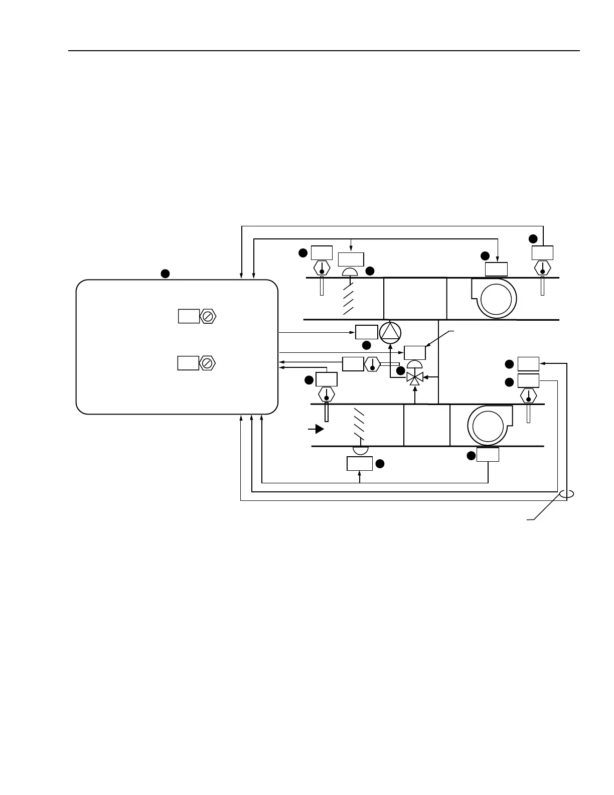
YEAR-ROUND HEAT RECOVERY PREHEAT SYSTEM CONTROL
Functional Description
100
OA
SA
RA
EA
ON
ON
ON
N.C.
PERCENT OPEN
TO SUPPLY COIL
N.C.
N.C.
N.O.
C
SUPPLY
COIL
SETPOINT
SUPPLY FAN
HEATING SETPOINT DETERMINED
BY SUPPLY SYSTEM CONTROLS.
M10474
1
2
8
9
3
10
5
6
7
4
11
12
OPEN
OPEN
79
86
82
55
75
82
EXHAUST
COIL
PUMP
PUMP START SETPOINTS:
COOLING SETPOINT = ANYTIME OA
TEMPERATURE IS DEGREES
ABOVE RA TEMPERATURE.
HEATING SETPOINT = ANYTIME OA
TEMPERATURE IS DEGREES
BELOW SA TEMPERATURE SETPOINT
DETERMINED BY SUPPLY
SYSTEM CONTROL.
3
6
Item
No. Function
1,2 Fans start and enable pump control upon
HVAC demand for ventilation (See FAN
SYSTEM START-STOP CONTROL).
3,4 Dampers close upon fan shutdown.
5 Pump runs when temperature conditions are
suitable for beneficial results.
6,10 The OA and RA temperature difference
determines when pump operation is beneficial.
2 Coil No. 2 valve is closed.
3 Coil No. 3 is modulating and provides a 5°F
temperature rise to the desired supply
temperature.
7Mixing valve prevents too much RA heat
from being transferred such that the SA
temperature exceeds that demanded by the
HVAC control system. Mixing valve also
keeps water entering the exhaust coil from
dropping below freezing to prevent the coil
from frosting.
8,9 HVAC system SA temperature setpoint
determines valve position in winter.
11 Operator information.
12 Dynamic graphic sequence display permits
the operator to adjust program setpoints.