ENGINEERING CMANUAL OF AUTOMATION CONTROL
AIR HANDLING SYSTEM CONTROL APPLICATIONS
237
CONDITION FOR SUCCESSFUL OPERATION
The water must be supplied at a reasonably constant pressure.
LIMITATIONS
Modulating water flow through a constant air volume chilled
water coil usually causes a rise in space RH because the coil
leaving water temperature rises significantly.
SPECIFICATIONS
The flow of chilled water through the cooling coil shall be
controlled by a three-way valve modulated by a space
temperature PI control loop. The valve shall close to the coil
upon fan shutdown and open to the coil upon loss of actuator
motive force.
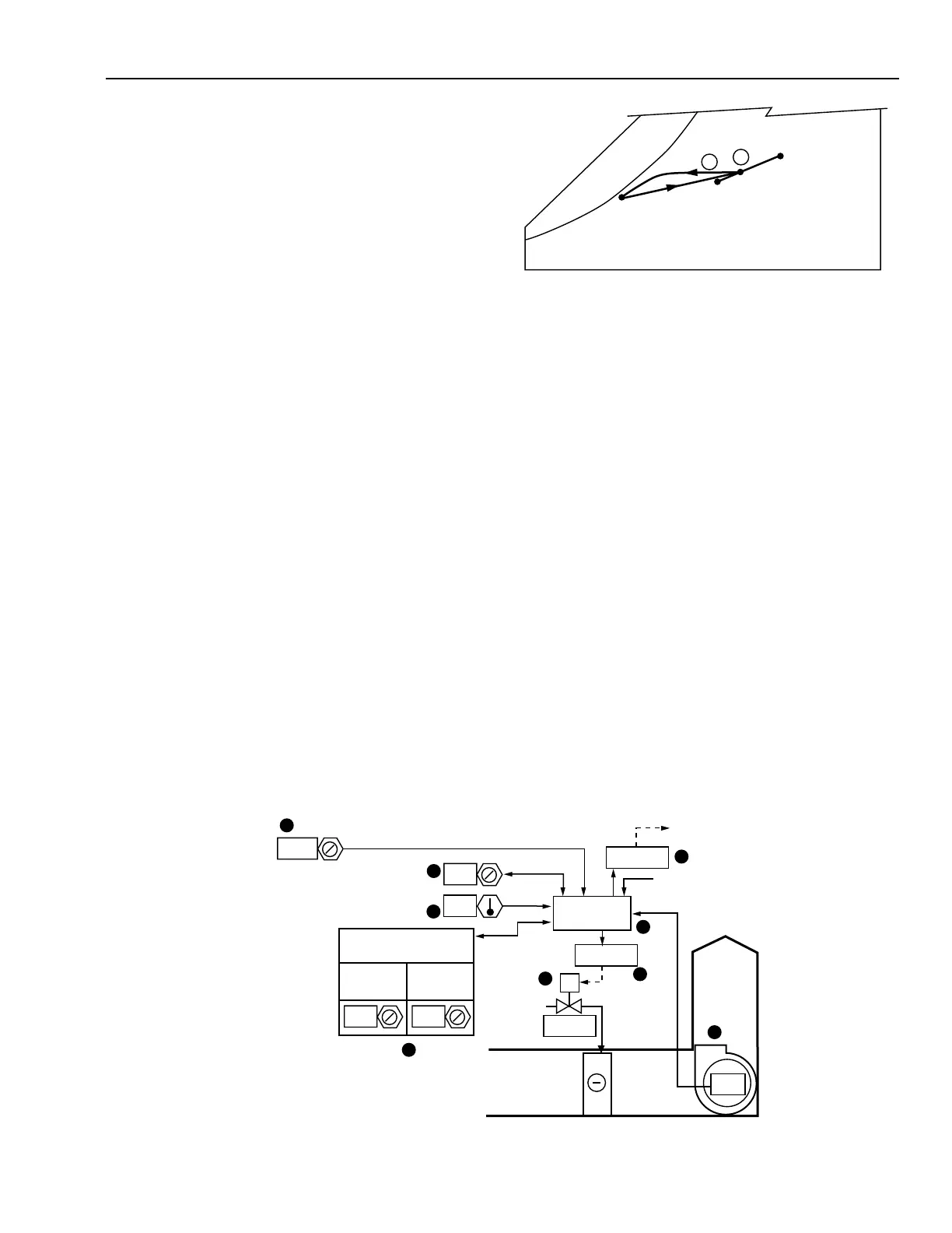
PSYCHROMETRIC ASPECTS
The temperature, and often moisture content, of leaving air
increases as the sensible cooling load lightens.
In the following chart it is assumed that:
1. Desired space and RA condition is 78°F DB and 50%
RH (65°F WB).
2. Design OA temperature is 95°F DB and 75°F WB.
3. Air entering the system is from the ECONOMIZER
CYCLE DECISION application. This system operates
on 35 percent OA during the cooling cycle.
4. Coil discharge temperature is 55°F.
C2558-2
OA 95°F DB,
75°F WB
RA 78°F DB,
50% RH
SA 55°F DB
2
1
MA
TWO-POSITION CONTROL OF DIRECT EXPANSION COIL SYSTEM
Functional Description
The following results are obtained:
Item
No. Explanation
1Mixed air temperature at cooling design
condition.
2Air entering the coil is cooled along a line of
constant moisture content until saturation is
approached. Near saturation the moisture
content is reduced as the air is cooled. This
process involves both latent and sensible
cooling.
NOTE: Condition of coil leaving air will change with the
cooling load in the space. As the cooling load
decreases, the three-way valve will provide less chilled
water flow to the coil and the discharge air temperature
will rise (approximately along Line 2).
M10470
4
MA
SA
ON
1
8
8
10
MINIMUM
ON TIME
MINIMUM
OFF TIME
COMPRESSOR
(MINUTES)
6
9
5
RELAY
RELAY
OPEN
CONTROL
PROGRAM
3
7
2
76
2.5
76
SUPPLY
FAN
TEMPERATURE CONTROL
DIFFERENTIAL (DEGREES)
TO COMPRESSOR
START CIRCUIT
COMPRESSOR
VOLTAGE MONITOR