ENGINEERING MANUAL OF AUTOMATIC CONTROL
CHILLER, BOILER, AND DISTRIBUTION SYSTEM CONTROL APPLICATIONS
331
–Steam or air atomizing burners use high pressure air or
25 psig steam to break up the oil into fine droplets.
For modulating or high/low flame control applications the
rotary or steam/air atomizing burners are most common.
GAS BURNERS
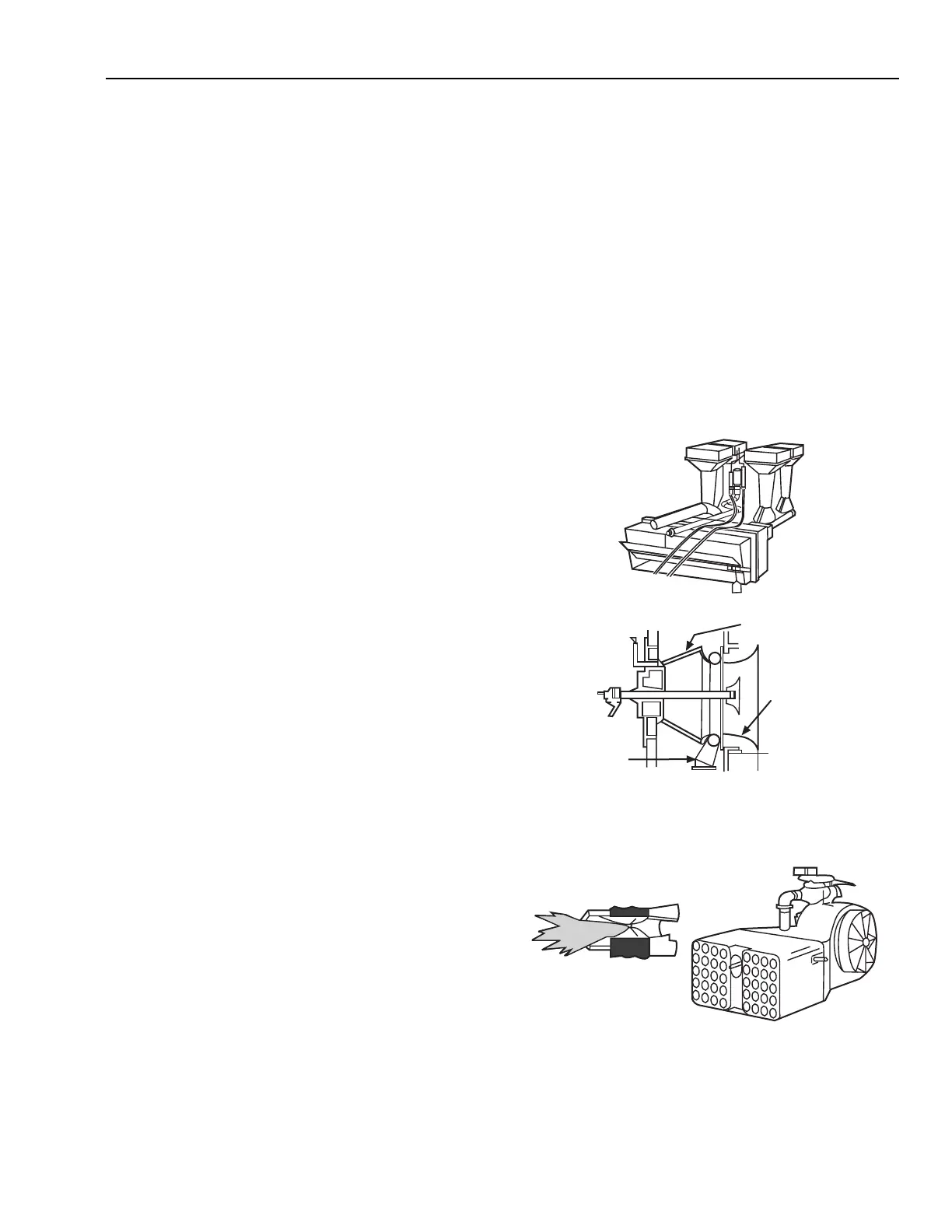
Two typical types of gas burners are the atmospheric injection
burner and the power type burner. The atmospheric injection
burner uses a jet of gas to aspirate combustion air and is
commonly used in home gas furnaces and boilers. The raw-gas
ring burner (Fig. 42) is an atmospheric injection burner.
Power burners (Fig. 43) use a forced-draft fan to thoroughly
mix air and gas as they enter the furnace. They are common in
commercial and industrial applications.
COMBUSTION IN BOILERS
PRINCIPLES OF COMBUSTION
When gas, oil, or other fuels are burned, several factors must
be considered if the burning process is to be safe, efficient, and
not harmful to the environment. The burning process must:
1. Provide enough air so that combustion is complete and
undesirable amounts of carbon monoxide or other
pollutants are not generated.
2. Avoid excess air in the fuel-air mixture which would result
in low efficiency.
3. Provide complete mixing of air with fuel before
introducing the mixture into the firebox.
4. Provide safety controls so that fuel is not introduced without
the presence of an ignition flame or spark and that flame is
not introduced in the presence of unburned fuel.
5. Avoid water temperatures below the dewpoint of the flue
gas to prevent condensation on the fireside of the boiler.
FLUE GAS ANALYSIS
Combustion can be monitored by flue gas analysis. For large
boilers, over 1,000,000 Btuh, the analysis is typically
continuous. For small boilers, flue gas is analyzed periodically
using portable instruments.
Flue gas composition analysis routinely measures the percent
of CO
2
(carbon dioxide) or O
2
(oxygen), but not both. Ideal
CO
2
is in the 10 to 12 percent range. Percent oxygen is the
most reliable indication of complete combustion. The ideal O
2
concentration is in the three to five percent range. Lower
concentrations are impractical and often unsafe. Higher O
2
concentrations mean that an excessive quantity of air is admitted
to the combustion chamber and must be heated by the fuel.
This excess air passes through the boiler too quickly for the
heat to be efficiently transferred to the water or steam. Carbon
dioxide measuring instruments are simpler or lower cost than
O
2
measuring instruments.
The CO
2
or O
2
concentration plus stack temperature provide
a burner efficiency in percent either directly or by means of
charts. This efficiency indicates only the amount of heat
extracted from the fuel. It does not account for excess heating
of combustion air or losses from leaks or the boiler jacket.
OIL BURNERS
Oil burners are usually of the atomizing variety, that is, they
provide a fine spray of oil. Several types exist:
– Gun type burners spray oil into a swirling air supply.
– Horizontal rotary burners use a spinning cup to whirl oil
and air into the furnace.
Fig. 42. Raw Gas Ring Burner.
A. BURNER ASSEMBLY
A. BURNER DETAILS
INSULATED
AIR REGISTER
TILE
GAS
INLET
C2902
DETAIL OF INDIVIDUAL
PORT
C2903
Fig. 43. Multiport Forced-Draft Gas Burner.